Table of Contents
Advertisement
Quick Links
Advertisement
Table of Contents
Troubleshooting

Related Manuals for power automation PA 8000 EL


Summary of Contents for power automation PA 8000 EL
- Page 1 PA 8000 EL Installation instructions CNC control unit...
- Page 2 Power Automation GmbH CNC-Automatisierungstechnik Gottlieb-Daimler-Str. 17/2 74385 Pleidelsheim Germany Telephone: +49-7144-899-0 Fax: +49-7144-899-299 email: info@powerautomation.com Internet: www.powerautomation.com Original installation instructions Option: PA 8000 EL PRO-SDI / PA 8000E EL PRO-SDI Version 2.0 ©2015 Power Automation GmbH 24.09.2015...
-
Page 3: Table Of Contents
PA 8000 EL CNC control unit Table of contents Table of contents General information............. 7 Information on this manual.......... 7 Explanation of symbols..........7 Limitation of liability............9 Copyright..............9 Warranty terms............9 Customer service............10 Glossary..............10 Safety.................. 11 Customer's responsibility........... - Page 4 PA 8000 EL CNC control unit Table of contents 3.3.1.4 Handwheel I/O............34 3.3.2 Digital outputs............37 3.3.2.1 Output interfaces..........37 3.3.2.2 Output characteristics........... 41 3.3.2.3 Output schematic..........42 3.3.3 Power connection............ 43 3.3.4 Module 2416 EL LEDs..........46 SDI interface.............. 47 PC connectors............
- Page 5 PA 8000 EL CNC control unit Table of contents Maintenance............... 87 Safety notes............... 87 Maintenance schedule..........87 Measures after maintenance........88 Troubleshooting..............89 Safety notes............... 89 Malfunction indicators..........90 8.2.1 Module 2416 EL LEDs..........91 Troubleshooting chart..........93 Service and return process..........95 Service...............
- Page 6 PA 8000 EL CNC control unit Table of contents 24.09.2015 | 6...
-
Page 7: General Information
PA 8000 EL CNC control unit General information 1 General information 1.1 Information on this manual General Information This installation manual provides important information on how to work with the control unit safely and efficiently. The installation manual is part of the control unit, must always be kept in the control unit's direct proximity and should be available for the personnel at any time. - Page 8 PA 8000 EL CNC control unit General information … emphasizes useful hints and recommendations as well as information for efficient and trouble-free opera- tion. Special Safety Notes The following symbols are used in connection with the safety notes to highlight particular dangers: DANGER! …...
-
Page 9: Limitation Of Liability
Apart from this, the obligations agreed upon in the delivery con- tract, the general terms and conditions, and the delivery conditions of Power Automation and the legal regulations valid at the time of contract apply. We reserve the right to make technical modifications in order to improve usability. -
Page 10: Customer Service
Our Customer Service is always available for technical information. For information on whom to contact by phone, fax, e-mail or via the internet, see Power Automation's address on page 2. Additionally, Power Automation staff is always interested in receiving new information and experiences resulting from the use of our products, which could be of great value for future improve- ments. -
Page 11: Safety
PA 8000 EL CNC control unit Safety 2 Safety 2.1 Customer's responsibility The control unit is used for commercial purposes. The operating company is thus subject to the legal obligations concerning indus- trial safety. The safety, accident prevention and environmental protection regu-... -
Page 12: Personnel Requirements
PA 8000 EL CNC control unit Safety 2.2 Personnel requirements 2.2.1 Qualifications WARNING! Danger of injury in case of insufficient qualifica- tion! Improper operation can lead to severe personal inju- ries and/or material damage. – Only those persons who have been specified in the corresponding chapters of this installation manual should be entrusted with the listed types of work. -
Page 13: Intended Use
The control unit is to be used exclusively to control CNC machines of a supported number of axes which are in accordance with the types cleared by Power Automation. Prerequisite for the intended use of the control unit is proper configuration as described in the installation manuals provided by Power Automation. -
Page 14: Unintended Use
PA 8000 EL CNC control unit Safety 2.4 Unintended use Unintended Use WARNING! Beware of unintended use! – In particular, avoid using the control unit for the fol- lowing purposes as these are regarded as not intended: – Operation using software not approved by Power Automation. -
Page 15: Specific Dangers
PA 8000 EL CNC control unit Safety Ear protection for protection of the ears during the work. Wear the ear protection always until the work is finished. Ground strap for protection of components susceptible to electrostatic discharge. Wear the ground strap on your wrist and connect it to a suitable equipotential bonding. - Page 16 PA 8000 EL CNC control unit Safety Only operate the CNC machine when the safety relay has been properly integrated into the machine emergency stop chain. Only let qualified personnel ( Ä Chapter 2.2.1 “Qualifications” on page 12) set up the emergency stop chain.
-
Page 17: Safety Devices
PA 8000 EL CNC control unit Safety 2.7 Safety devices Safety DANGER! Malfunctioning safety devices may pose a fatal risk! Safety devices must be intact and properly integrated into the control unit's configuration and software in order to guarantee safety. -
Page 18: Cnc Ready' Signal - Emergency Stop Interlocking
PA 8000 EL CNC control unit Safety Further Applicable Documents For information on the machine's safety devices and emergency stop chain see the manual provided by the CNC machine's manufacturer. The manufacturer of the CNC machine is responsible for the proper installation of the emergency stop. -
Page 19: Power Ok' Signal
PA 8000 EL CNC control unit Safety 2.8.2 'Power ok' signal The "Power ok" relay is triggered by the hardware monitoring of the internal supply voltages and the temperature sensor. The "Power ok" relay is switched off when the power supplies do not match the allowed range or the internal temperature is too high. -
Page 20: Data Safety
Ensure that backups are updated manually in case of modifi- cations to the configuration. 2.10.2 System protection Initial State Automated regular anti-virus scanning and manual scanning of files copied to the control unit are advised by Power Automation as needed. 24.09.2015 | 20... - Page 21 PA 8000 EL CNC control unit Safety To protect the system against virus attacs or other system failures, it is recommended to take the following measures: Either work without the CNC without Internet connection or assure it is connected via a managed firewall.
-
Page 22: Environmental Protection
PA 8000 EL CNC control unit Safety Fig. 2: Overview FBWF interface 2.11 Environmental protection CAUTION! Environmental hazard caused by incorrect han- dling! Incorrect handling of environmentally hazardous sub- stances, especially incorrect waste disposal, can cause considerable damage to the environment. -
Page 23: Labels
Electronic Components Electronic components are considered special waste. They must be properly disposed of. Power Automation will accept the control unit to properly dispose of its components upon decommissioning. Follow the standard return procedure, as described in Ä Chapter 9.3 “Return policy and procedure” on page 97. - Page 24 PA 8000 EL CNC control unit Safety Type Plate The type plate includes the following information: Manufacturer address 'CE'-sign Control unit model Serial number Article number Connection values Fig. 4: Type Plate (Example) Operating System Product Key The label affixed to the side of the control unit next to the type plate provides the operating system's product key.
- Page 25 New CNC Installation Folder The CNC installation folder has been changed. Formerly, every- thing had been installed in c:\program files\power automation. In Windows 7 (W7) it is installed under c:\pacnc. This is also true for the files, which are written from the CNC software on d:\ partition.
- Page 26 PA 8000 EL CNC control unit Safety 24.09.2015 | 26...
-
Page 27: Design And Function
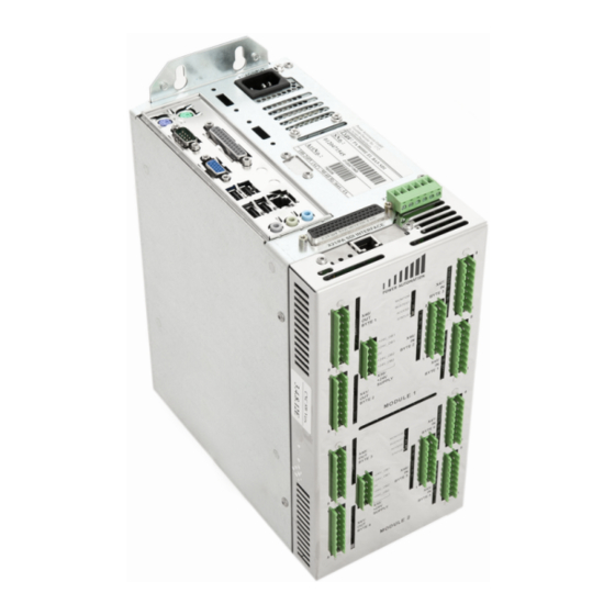
PA 8000 EL CNC control unit Design and function 3 Design and function 3.1 Overview Fig. 6: Overview (Top) Safety connector (X19) PC connectors Superbus connector (X13) SDI connector (X21) 3.2 Brief description The PA8000 EL is an open architecture CNC control unit providing numerical interface for the PA-SDI drive. -
Page 28: Module 2416 El
PA 8000 EL CNC control unit Design and function 3.3 Module 2416 EL The control unit has optionally one or two 2416 EL module(s). Each module has 24 digital inputs and 16 digital outputs (24V DC). The inputs and outputs are fully opto-isolated from the internal logic. -
Page 29: Digital Inputs
PA 8000 EL CNC control unit Design and function 3.3.1 Digital inputs 3.3.1.1 Input interfaces Overview Fig. 8: Input bytes 10 Input byte 2 (X46) 11 Input byte 1 (X45) 12 Input byte 3 (X47) The inputs are grouped in bytes (8 signals). - Page 30 PA 8000 EL CNC control unit Design and function Connection Fig. 9: Reference pin power connector Each byte is connected with an 8 pole terminal block. The conductor cross-section of the wire must be 0.3 to 1.75 (AWG 22 to 15).
- Page 31 PA 8000 EL CNC control unit Design and function Pin Assignment Fig. 10: Pin assignment Byte 1 +24 V input Byte 2 +24 V input Byte 3 +24 V input pin 1 1. input bit pin 1 9. input bit pin 1 17.
- Page 32 PA 8000 EL CNC control unit Design and function Input Status LEDs Fig. 11: Input status LEDs The input LEDs are located in the circuit's input path and therefore show the real state of the 24 V inputs. A HIGH input signal causes the corresponding LED to turn ON.
-
Page 33: Input Characteristics
PA 8000 EL CNC control unit Design and function 3.3.1.2 Input characteristics Property Value Unit Number of inputs Maximum input DC voltage 27 V Input current at 24 V / 5 V (typical) < 3 mA Power dissipation at 24 V / 5 V per <... -
Page 34: Input Schematic
PA 8000 EL CNC control unit Design and function 3.3.1.3 Input schematic This figure shows how the inputs are realized on each 2416 EL module. Fig. 12: Input equivalent schematic Input n+1 Logic CNC superbus Input n 3.3.1.4 Handwheel I/O On each 2416 EL input/output module two special inputs for hand- wheel connections are provided. - Page 35 PA 8000 EL CNC control unit Design and function Required Handwheel Specifications Property Value Unit Supply level 24 V DC Signal level 24 V DC Encoder signals Track 'A' and 'B' (shifted 90°) Only handwheels with A/B signals can be used. No 'Pulse/Direction' signals are supported.
- Page 36 PA 8000 EL CNC control unit Design and function Wiring Schematic Fig. 13: Wiring schematic handwheel inputs Handwheel Power supply connector Input byte 3 The ground of the power supply used for the hand- wheel must be connected to the one of the power sup- plies of the 2416 EL module (connector X30, pin 3).
-
Page 37: Digital Outputs
PA 8000 EL CNC control unit Design and function 3.3.2 Digital outputs 3.3.2.1 Output interfaces Overview Fig. 14: Output bytes Output byte 1 (X41) Output byte 2 (X40) The outputs are grouped in bytes (8 signals). 24.09.2015 | 37... - Page 38 PA 8000 EL CNC control unit Design and function Connection Fig. 15: Reference pin power connector Each byte is connected with an 8 pole terminal block. Each output byte has its own power supply connection. This feature can be used to turn off a whole byte using an external switch.
- Page 39 PA 8000 EL CNC control unit Design and function Pin Assignment Fig. 16: Pin assignment Byte 1 +24 V output Byte 2 +24 V output pin 1 1. output bit pin 1 9. output bit pin 2 2. output bit pin 2 10.
- Page 40 PA 8000 EL CNC control unit Design and function Output Status LEDs Fig. 17: Output status LEDs The output LEDs are located directly in the output path and there- fore show the real state of the 24 V outputs. If the outputs are ON, the corresponding LEDs are ON.
-
Page 41: Output Characteristics
PA 8000 EL CNC control unit Design and function 3.3.2.2 Output characteristics Property Value Unit Number of outputs Max. continuous output DC per pin Max. total continuous output current per byte Power dissipation 0.20 W per pin at 24 V for 0.5 A Power dissipation 0.45 W... -
Page 42: Output Schematic
PA 8000 EL CNC control unit Design and function 3.3.2.3 Output schematic This figure shows how the outputs are realized on each 2416 EL module. Fig. 18: Module 2416 EL output schematic Supplied from PCI Superbus board Output supply input (-15 % - +12.5 %) -
Page 43: Power Connection
PA 8000 EL CNC control unit Design and function 3.3.3 Power connection Overview Fig. 19: Power supply connector + 24 V DC Each of the 2416 EL modules needs a separate + 24 V DC power supply for its DC outputs (connector X30). - Page 44 PA 8000 EL CNC control unit Design and function Pin Assignment Fig. 20: Power supply pins Each module has a 5 pin connector (X30) with the following pin assignment: Pin (Fig. 20) Assignment Pin 1 + 24 V power supply for output byte 1...
- Page 45 PA 8000 EL CNC control unit Design and function Notes Pin 1 and 2 are connected internally. Pin 4 and 5 are connected internally. Reference for all is pin 3 (0 V). With pins 1 and/or 2 and pins 4 and/or 5 the output bytes are supplied separately.
-
Page 46: Module 2416 El Leds
PA 8000 EL CNC control unit Design and function 3.3.4 Module 2416 EL LEDs Overview The 2416 EL module has four LEDs for diagnostic purposes. Fig. 21: Status LEDs Status Access Bustest Monitor For a detailed assignment of the LEDs' states see Ä... -
Page 47: Sdi Interface
PA 8000 EL CNC control unit Design and function 3.4 SDI interface Overview Fig. 22: SDI connector positions Safety connector (X19) PC connectors Superbus connector (X13) SDI connector (X21) The hardware provides a single RJ 45 connector which is deter- mined at connector X21 (Fig. - Page 48 PA 8000 EL CNC control unit Design and function Connection Requirements SDI drives must be wired toward the control unit's SDI connector in a daisy chain setup. Fig. 23: Daisy chain setup PA 8000 EL (control unit) PA SDI Drive Midi...
-
Page 49: Pc Connectors
PA 8000 EL CNC control unit Design and function 3.5 PC connectors Overview The control unit provides a number of standard PC interface con- nectors for various input and output applications. Fig. 24: Overviews PC connectors Main power supply (X1) - Page 50 PA 8000 EL CNC control unit Design and function (X1) Main Power Supply (1) Always use the line cable delivered with the control unit. Ensure, that the line cable is only connected to either 115 V AC or 230 V AC.
- Page 51 PA 8000 EL CNC control unit Design and function (X4) VGA Connector (2) The control unit is equipped with a VGA connector to connect graphic displays. Only use either with PA operator's panels or a standard VGA compatible monitor. Fig. 26: VGA connector (Sub-D 15)
- Page 52 PA 8000 EL CNC control unit Design and function (X4) DVI Connector (15) Digital Visual Interface (DVI) is a video display interface developed by the Digital Display Working Group (DDWG). The digital interface is used to connect a video source, such as a display controller to a display device, such as a computer monitor.
- Page 53 PA 8000 EL CNC control unit Design and function Assignment (Fig. 27) GREEN BLUE SYNC USB 2.0 Connectors (4) The USB ports allow connection of USB peripherals. The control unit includes 3 standard USB 2.0 type A ports. Fig. 28: USB connectors (Type A)
- Page 54 PA 8000 EL CNC control unit Design and function Ethernet Connector (5) The Ethernet connector allows connection of the control unit to local area networks. Fig. 29: Ethernet connector (RJ 45) NOTICE! Malfunctions and damage to the control unit! The control unit provides one RJ 45 connector. It is Ä...
-
Page 55: Safety Connector
For standard conforming distinction use wire sheathed in yellow/green. 3.6 Safety connector Overview All PA 8000 EL models have two relays for safety functions. The connector provides both a normally closed and a normally open contact for each relay. The safety contacts are located on connector X19. -
Page 56: Safety Connector Specification
PA 8000 EL CNC control unit Design and function Safety Connector Location Fig. 31: Safety connector location (model "Analog/SDI") Safety connector X19 Purpose / Wiring For information regarding the safety connector's purpose and Ä Chapter 2.8 “Machine safety” on page 17 wiring examples see Ä... - Page 57 PA 8000 EL CNC control unit Design and function Relay 1 "Power ok" The first relay is called "Power ok" and switches when the following conditions are met: The power supply voltages are in operating range. The operating temperature is below +60 °C (+140 °F)
- Page 58 PA 8000 EL CNC control unit Design and function Relay 2 "CNC ready" The second relay is called "CNC ready" and switches when the fol- lowing conditions are met: The control unit is ready when: – The watchdog is re-triggered.
-
Page 59: Safety Connector Schematic
PA 8000 EL CNC control unit Design and function 3.6.2 Safety connector schematic Fig. 33: Safety connector equivalent schematic 3.7 (X20) PA USB software dongle connector Fig. 34: PA USB software dongle connector An additional USB port is specially marked as "PA dongle port"... -
Page 60: Pamio Interface (Superbus)
A variety of I/O and axes extension modules (PAMIO) can be connected to the connector. Fig. 35: Superbus connector Fig. 36: Location superbus connector Every PA 8000 EL model has a PAMIO superbus connector located on the PCI interface board. For further information see Ä Chapter 3.8.1 “PAMIO boxes and modules”... -
Page 61: Pamio Boxes And Modules
PA 8000 EL CNC control unit Design and function 3.8.1 PAMIO boxes and modules Basic Description Fig. 37: PAMIO superbus schematic control unit PA superbus connection PAMIO box with two analog axes modules PA superbus connection termination plug max. chain length (14 PAMIO boxes/30 m (98 ft)) A PAMIO box consists of its housing, the PA superbus input and output connectors as well as two plug-in-slots for I/O modules. - Page 62 PAMIO boxes are shipped without connection cables. Cables of the following lengths can be ordered from Power Automation: 2 m (6.5 ft), 5 m (16.5 ft), 10 m (33 ft), 20 m (66 ft), 25 m (82 ft) (see Ä Chapter 9 “Service and return process” on page 95).
- Page 63 PA 8000 EL CNC control unit Design and function PAMIO 2416 Feature Value Specifications digital inputs 24 (3 bytes) 24 V DC digital outputs 16 (2 bytes) 24 V DC isolation optical PAMIO 4ENC4A Feature Value Specifications encoder inputs analog inputs...
- Page 64 PA 8000 EL CNC control unit Design and function 24.09.2015 | 64...
-
Page 65: Technical Data
PA 8000 EL CNC control unit Technical data 4 Technical data 4.1 General specifications General Information Property Value Unit Dimensions 123.5 x 300 x 225 (WxDxH) 4.86 x 11.81 x 8.56 inch Weight 7.94 4.2 Connection values Electrical Property Value Unit... -
Page 66: Operating Conditions
PA 8000 EL CNC control unit Technical data 4.3 Operating conditions General Property Value Unit Operating temperature +5 - +45 °C +41 - +113 °F Storage temperature -20 - +60 °C -4 - +140 °F Temperature gradient (within 10 10 °C minutes) 50 °F... -
Page 67: Dimension Sheet
PA 8000 EL CNC control unit Technical data 4.4 Dimension sheet Fig. 39: dimension sheet 24.09.2015 | 67... -
Page 68: Electromagnetic Compatibility
PA 8000 EL CNC control unit Technical data The dimensions are given in milimeters and in inches in parentheses. 4.5 Electromagnetic compatibility The control unit meets the requirements specified in the following standards: Safety Of Machinery Standard Title Requirement Value... -
Page 69: Installation Guidelines
PA 8000 EL CNC control unit Technical data Interference Resistance Standard Title Requirement Value IEC / EN 61000-6-2 [...] Immunity standard for industrial environments EN 61000-4-2 [...] Electrostatic discharge immunity ESD air discharge 8 KV [...] contact discharge 4 KV EN 61000-4-3 [...] Radiated, radio-frequency, electro-... - Page 70 PA 8000 EL CNC control unit Technical data Reference potential and ground of all electrical operating supplies Installation parts and cabinets with your CNC control unit have to be connected in star topology with the isolation/protected ground conductor system to avoid ground loops.
- Page 71 PA 8000 EL CNC control unit Technical data Shielding Of Conductors Electrical, magnetic and electromagnetic interference fields are weakened by means of shielding Via the shielding rail, which is connected with low impedance to the rack, interference currents are shorted by the cable shield to the ground.
- Page 72 PA 8000 EL CNC control unit Technical data 24.09.2015 | 72...
-
Page 73: Installation
PA 8000 EL CNC control unit Installation 5 Installation Safety WARNING! Danger of injury due to improper installation and commissioning! Improper installation and commissioning can result in severe personal injury or material damage. Prior to beginning installation, ensure that there is sufficient space to work. -
Page 74: Electrical Cabinet Structural Requirements
PA 8000 EL CNC control unit Installation 5.1.2 Electrical cabinet structural requirements The control unit must be installed in an electrical cabinet meeting the following minimum requirements. Requirement Value IP protection class IP 54 (DIN 40050/ IEC 60529) Mounting hole sizes and... -
Page 75: Mounting The Control Unit In A Cabinet
PA 8000 EL CNC control unit Installation 5.2 Mounting the control unit in a cabinet Mounting Orientation Fig. 40: Mounting orientation Always mount the control unit as shown in Fig. 40. The dimensions are given in milimeters and in inches in parentheses. - Page 76 PA 8000 EL CNC control unit Installation Spacing Most of the CNC connectors (axes and inputs/outputs) are located on the front side. Ensure that there is clearance of at least 50 mm (2 inches) to allow accessibility to the connectors.
- Page 77 PA 8000 EL CNC control unit Installation Top / Bottom Spacing All PC connectors (PS2, VGA, USB, etc.) and some CNC connectors (X13/X19) are located on the top side. Ensure that there is clearance of at least 100 mm (4 inches) to allow accessibility to the connectors.
- Page 78 PA 8000 EL CNC control unit Installation Fig. 42: Top/bottom spacing 24.09.2015 | 78...
- Page 79 PA 8000 EL CNC control unit Installation Service access For service or maintenance purposes access to the control unit may be necessary. Install the control unit and adjacent components in a way that allows for access to all mounting points, cables etc. by service personnel.
-
Page 80: Installing Digital I/O
Due to the versatility of the control unit not all possible configuration options can be covered in detail. If in doubt, contact the Power Automation's customer support. Ä Chapter 9 “Service and return For contact information see process”... -
Page 81: Wiring For Machine Safety
PA 8000 EL CNC control unit Installation Personnel: Skilled electrician Set up inputs according to the schematic. Set up outputs according to the schematic. Set up power supply for outputs. Ensure that the circuit is protected by a fuse of appropriate ratings. -
Page 82: Wiring Example For 'Cnc Ready' Relay
PA 8000 EL CNC control unit Installation 5.4.1 Wiring example for 'CNC ready' relay Emergency Stop Interlocking DANGER! Injuries due to uncontrolled operation! An inactive 'CNC Ready' signal represents a safety related situation. The "CNC Ready" relay is switched off when the PA CNC control unit is in a situation where the axes' movements are not controlled. -
Page 83: Wiring Example For 'Power Ok' Relay
PA 8000 EL CNC control unit Installation 5.4.2 Wiring example for 'Power ok' relay Power Supply Interlocking The "Power ok" relay is triggered by the hardware monitoring of the internal supply voltages and the temperature sensor. The "Power ok" relay is switched off when the supply voltages do not match the allowed range or the internal temperature is too high. - Page 84 PA 8000 EL CNC control unit Installation 24.09.2015 | 84...
-
Page 85: Transport, Packaging And Storage
PA 8000 EL CNC control unit Transport, packaging and storage 6 Transport, packaging and storage 6.1 Transport Inspection Check the delivery immediately on receipt for completeness and transport damage. Record the extent of transport damage in the transport documents or on the delivery note of the forwarding agent. -
Page 86: Storage
PA 8000 EL CNC control unit Transport, packaging and storage Dispose of packaging materials in an environmentally respon- sible manner. Follow the locally valid waste disposal regulations. If necessary employ a special waste disposal company to dispose of pack- aging material. -
Page 87: Maintenance
Personnel Some maintenance tasks can only be executed by trained qualified personnel, or only by Power Automation. In these cases this is separately indicated in the description of the specific maintenance tasks. All work on the electrical equipment shall only be executed by a qualified electrician. -
Page 88: Measures After Maintenance
PA 8000 EL CNC control unit Maintenance Schedule Interval Maintenance work Personnel Once a year Visual check, whether all fan exhausts are clean and the fans are Instructed person properly working. If required, clean the fan exhausts with a dry cloth or if necessary use a vacuum cleaner. -
Page 89: Troubleshooting
Observe the personnel requirements for repairs specified in the troubleshooting chart. If in doubt, contact Power Automation for help or support by an authorized service technician. Ensure that the power supply has been disconnected. -
Page 90: Malfunction Indicators
PA 8000 EL CNC control unit Troubleshooting In Case Of Faults The following general rules apply: Personnel: Qualified personnel Protective equipment: Ground strap ESD safety shoes ESD safety pad ESD clothing Protective glasses Ear protection Antistatic gloves In the event of faults that pose immediate danger to man or machine, activate the emergency shutoff function immedi- ately. -
Page 91: Module 2416 El Leds
PA 8000 EL CNC control unit Troubleshooting 8.2.1 Module 2416 EL LEDs Overview The 2416 EL module has four LEDs for diagnostic purposes. Fig. 47: Status LEDs Status Access Bustest Monitor The LEDs' states are assigned the following status messages:... - Page 92 PA 8000 EL CNC control unit Troubleshooting LED "Monitor" (1) LED state Module status Error 1: The ambient temperature is above 60 °C (140 °F) and all outputs are disabled by the onboard logic OR Error 2: The watchdog is re-triggered but the 24 V output supply has been interrupted for more than 60 seconds.
-
Page 93: Troubleshooting Chart
If in doubt regarding listed repairs, contact Power Automation for help. Return procedure In the event of an error that requires the control unit to be sent to Power Automation, follow the instructions Ä Chapter 9.3 “Return policy and procedure” given in on page 97. - Page 94 PA 8000 EL CNC control unit Troubleshooting Troubleshooting Chart Error Cause Solution Personnel Unscheduled Overheating Ensure that all requirements Skilled electrician shutdown regarding spacing within the cabinet are met ( Ä Chapter 5.2 “Mounting the control unit in a cabinet”...
-
Page 95: Service And Return Process
CNC system to your network for world-wide-web access. Power Automation provides a remote control software which allows our service staff to log into your CNC. This provides all the informa- tion available on the machine. They can check all the data like the PLC program, machine parameters, or the NC programs directly on the real system under real conditions. - Page 96 PA 8000 EL CNC control unit Service and return process Power Automation America, Inc. 8601 Jameel Road, Suite 140 Houston, Texas 77040 USA Tel: +1-713-263-9400 Fax: +1-281-715-2500 sales.america@powerautomation.com Power Automation Office Turkey Kustepe Mah. Mecidiyekoy Yolu Cad. Trump Towers No. 12 Kule: 2 K:18...
-
Page 97: Spare Parts
Due to the high quality of our products we can assure you that you will not need this service often. Spare parts are often urgent so Power Automation provides the relevant spare parts at the local service centers for immediate dispatch. - Page 98 PA 8000 EL CNC control unit Service and return process Acquiring RMA Number Contact Power Automation to receive an RMA form in Excel Ä “RMA Form” on page 99 format. Open the 'RMA Process' form provided by Power Automa- tion.
- Page 99 PA 8000 EL CNC control unit Service and return process RMA Form Fig. 48: RMA Form 24.09.2015 | 99...
-
Page 100: Training
Service and return process Return Pack the goods properly. Controls must be packed in original or equivalent packaging. If the packaging is not proper, Power Automation will charge a packaging flat rate. NOTICE! Damages due to inadequate packaging Inadequate packaging may result in damages to the control unit. -
Page 101: Dismounting And Decommissioning
Decommissioning Electronic components are considered special waste. They must be properly disposed of. Power Automation will accept the control unit to properly dispose of its components upon decommissioning. To return the control unit follow the instructions given Ä Chapter 9.3 “Return policy and procedure”... - Page 102 PA 8000 EL CNC control unit Dismounting and decommissioning 24.09.2015 | 102...
-
Page 103: Ec Declaration Of Conformity
PA 8000 EL CNC control unit EC Declaration of Conformity 11 EC Declaration of Conformity EC Declaration of Conformity 24.09.2015 | 103... - Page 104 PA 8000 EL CNC control unit EC Declaration of Conformity Fig. 49: EC Declaration of Conformity 24.09.2015 | 104...
-
Page 105: Proof Of Change
PA 8000 EL CNC control unit Proof of change 12 Proof of change Proof Of Change Version Change Date Original Version 05/18/2015 24.09.2015 | 105... - Page 106 PA 8000 EL CNC control unit Proof of change 24.09.2015 | 106...
-
Page 107: Index
PA 8000 EL CNC control unit Index 13 Index Acceleration ......66 Humidity ....... 66 Air circulation . - Page 108 PA 8000 EL CNC control unit Index Service Addresses ..... . . 95 Shield ....... . . 79 Qualification Spacing .
Need help?
Do you have a question about the PA 8000 EL and is the answer not in the manual?
Questions and answers