Table of Contents
Advertisement
Quick Links
Advertisement
Table of Contents
Troubleshooting

Related Manuals for power automation PA 8000 LW


Summary of Contents for power automation PA 8000 LW
- Page 1 PA 8000 LW Installation instructions CNC control unit...
- Page 2 Power Automation GmbH CNC-Automatisierungstechnik Gottlieb-Daimler-Str. 17/2 74385 Pleidelsheim Germany Telephone: +49-7144-899-0 Fax: +49-7144-899-299 email: info@powerautomation.com Internet: www.powerautomation.com Original installation instructions Variante: PA 8000 LW PRO SDI-AN / PA 8000E LW PRO SDI-AN Version 2.0 ©2015 Power Automation GmbH 25.09.2015...
-
Page 3: Table Of Contents
PA 8000 LW CNC control unit Table of contents Table of contents General information..............7 Information on this manual..........7 Explanation of symbols............7 Limitation of liability............9 Copyright................9 Warranty terms..............9 Customer service............. 10 Glossary................11 Safety..................13 Customer's responsibility.......... - Page 4 PA 8000 LW CNC control unit Table of contents 3.3.1.1 Input interfaces............31 3.3.1.2 Input characteristics............ 32 3.3.1.3 Input schematic............33 3.3.1.4 RMS encoder wiring example........34 3.3.2 Analog Outputs............. 35 3.3.2.1 Output interfaces............35 3.3.2.2 Output characteristics..........36 3.3.2.3 Output schematic............
- Page 5 PA 8000 LW CNC control unit Table of contents Connection values............83 Operating conditions............84 Dimension sheet.............. 85 Electromagnetic compatibility.......... 87 Installation guidelines............88 Installation................91 Prerequisites and preparations........91 5.1.1 General requirements........... 91 5.1.2 Electrical cabinet structural requirements..... 92 5.1.3...
- Page 6 PA 8000 LW CNC control unit Table of contents Service and return process........... 119 Service................119 9.1.1 Service addresses............119 Spare parts..............121 Return policy and procedure.......... 121 Training................124 10 Dismounting and decommissioning........125 11 EC Declaration of Conformity..........127 12 Proof of change..............
-
Page 7: General Information
PA 8000 LW CNC control unit General information 1 General information 1.1 Information on this manual General Information This installation manual provides important information on how to work with the control unit safely and efficiently. The installation manual is part of the control unit, must always be kept in the control unit's direct proximity and should be available for the per- sonnel at any time. - Page 8 PA 8000 LW CNC control unit General information … highlights hazards caused by electric current. There is a L DANGER danger of serious injury or death if the safety notes are not com- plied with. Additional symbols and high- The following symbols and highlights are used to distinguish...
-
Page 9: Limitation Of Liability
Passing this installation manual on to third parties, duplication of any kind – even in form of excerpts – as well as the use and/or disclosure of the contents without the written consent of Power Automation is not permitted. Violations oblige to compensation. The right for further claims remains reserved. -
Page 10: Customer Service
For information on whom to contact by phone, fax, e-mail or via the internet, see Power Automation's address on page 2. Additionally, Power Automation staff is always interested in receiving new information and experiences resulting from the use of our prod- ucts, which could be of great value for future improvements. -
Page 11: Glossary
PA 8000 LW CNC control unit General information 1.7 Glossary CMOS - Complementary metal-oxide-semiconductor - Computerized Numerical Control - Delivered Duty Unpaid - Human Machine Interface The graphical user interface provided by the PA software. - Insulating Piercing Connector - Manual Data Input... - Page 12 PA 8000 LW CNC control unit General information 25.09.2015 | 12...
-
Page 13: Safety
PA 8000 LW CNC control unit Safety 2 Safety 2.1 Customer's responsibility The control unit is used for commercial purposes. The operating com- pany is thus subject to the legal obligations concerning industrial safety. The safety, accident prevention and environmental protection regula-... -
Page 14: Personnel Requirements
PA 8000 LW CNC control unit Safety 2.2 Personnel requirements 2.2.1 Qualifications Danger of injury in case of insufficient qualification! L WARNING – Only those persons who have been specified in the corre- sponding chapters of this installation manual should be entrusted with the listed types of work. -
Page 15: Intended Use
The control unit is to be used exclusively to control CNC machines of a supported number of axes which are in accordance with the types cleared by Power Automation. Prerequisite for the intended use of the control unit is proper configuration as described in the installation man- uals provided by Power Automation. -
Page 16: Personal Protective Gear
PA 8000 LW CNC control unit Safety 2.5 Personal protective gear Wearing of personal protective gear is required to minimize health haz- ards and damage when working with the control unit. Always wear the protective equipment that is necessary for the respective task when working. - Page 17 PA 8000 LW CNC control unit Safety Observe the safety instructions listed here, and the warnings in subsequent chapters of this installation manual, to reduce health hazards and to avoid dangerous situations. Danger to life caused by electric current! L DANGER Touching conductive parts causes a direct danger to life.
-
Page 18: Safety Devices
PA 8000 LW CNC control unit Safety Malfunction due to discharged buffer battery! L CAUTION The control unit's CMOS settings are buffered by a battery. If this battery is discharged completely the CMOS settings are lost. Mal- functions of the control unit may result. -
Page 19: Machine Safety
PA 8000 LW CNC control unit Safety 2.8 Machine safety Additional Information For information regarding the safety connector's specification and wiring examples see Ä Chapter 3.7 “Safety connector” on page 75 and Ä Chapter 5.5 “Wiring for machine safety” on page 102. -
Page 20: Power Ok' Signal
PA 8000 LW CNC control unit Safety 2.8.2 'Power ok' signal The "Power ok" relay is triggered by the hardware monitoring of the internal supply voltages and the temperature sensor. The "Power ok" relay is switched off when the power supplies do not match the allowed range or the internal temperature is too high. -
Page 21: Data Safety
Ensure that backups are updated manually in case of modifica- tions to the configuration. 2.10.2 System protection Initial State Automated regular anti-virus scanning and manual scanning of files copied to the control unit are advised by Power Automation as needed. 25.09.2015 | 21... - Page 22 PA 8000 LW CNC control unit Safety To protect the system against virus attacs or other system failures, it is recommended to take the following measures: Either work without the CNC without Internet connection or assure it is connected via a managed firewall.
-
Page 23: Environmental Protection
PA 8000 LW CNC control unit Safety Fig. 2: Overview FBWF interface 2.11 Environmental protection Environmental hazard caused by incorrect handling! L CAUTION Incorrect handling of environmentally hazardous substances, especially incorrect waste disposal, can cause considerable damage to the environment. -
Page 24: Labels
Electronic Components Electronic components are considered special waste. They must be properly disposed of. Power Automation will accept the control unit to properly dispose of its components upon decommissioning. Follow the standard return procedure, as described in Ä Chapter 9.3 “Return policy and procedure” on page 121. - Page 25 PA 8000 LW CNC control unit Safety Type Plate The type plate includes the following information: Manufacturer address 'CE'-sign Control unit model Serial number Article number Connection values Fig. 4: Type Plate (Example) Operating System Product Key The label affixed to the side of the control unit next to the type plate provides the operating system's product key.
- Page 26 – Never open the control unit, or you will lose your material warranty. – Always contact Power Automation, if extensions, repairs or modifi- cations are required (see Ä Chapter 9 “Service and return process” on page 119). Broken or removed seals void all material warranty provided by Power Automation.
-
Page 27: Design And Function
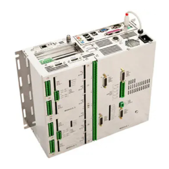
PA 8000 LW CNC control unit Design and function 3 Design and function 3.1 Overview Top View 25.09.2015 | 27... - Page 28 PA 8000 LW CNC control unit Design and function Fig. 6: Modules PC connectors [all models] Module 2416EL (2) [all models] Module 2416EL (1) [all models] Module 4AXLX [models with analog axes only] 25.09.2015 | 28...
-
Page 29: Brief Description
PA 8000 LW CNC control unit Design and function Model Configurations The PA 8000 LW is shipped in three different models containing the following modules and interfaces. Model Description PC connec- Module 2416EL Module 4AXLX tors PA 8000 LW SDI and analog... -
Page 30: Module 4Axlx
PA 8000 LW CNC control unit Design and function 3.3 Module 4AXLX Overview Not included in all models This module and its interfaces are only included in models with analog axes. The module 4AXLX provides an analog interface for up to four axes, each provided with a separate RMS input. -
Page 31: Digital Inputs
PA 8000 LW CNC control unit Design and function Pos. Label No. Function Measurement input 3. axis Status LEDs 3.3.1 Digital Inputs 3.3.1.1 Input interfaces Connectors Fig. 8: Input interfaces Pos. Label Function Connector Connector 1st axis 15 pin, sub-D, female... -
Page 32: Input Characteristics
PA 8000 LW CNC control unit Design and function Pin Assignment Fig. 9: Encoder input connector (X31/X32/X33/X34) Pins (Fig. 9) RMS Input Function Pin 1 Track A+ Pin 2 Track A- Pin 3 Track B+ Pin 4 Track B- Pin 5... -
Page 33: Input Schematic
PA 8000 LW CNC control unit Design and function Probe Inputs Property Value Unit Max. measurement input voltage 27 V Measurement input current (at 24 V) 7 mA Measurement input impedance 2200 Ω Measurement operating voltage 5 V DC max. -
Page 34: Rms Encoder Wiring Example
PA 8000 LW CNC control unit Design and function 3.3.1.4 RMS encoder wiring example RMS Encoder Wiring Example The following schematic demonstrates the recommended way of con- necting the CNC RMS inputs to the encoders (or any other device with incremental output). -
Page 35: Analog Outputs
PA 8000 LW CNC control unit Design and function 3.3.2 Analog Outputs 3.3.2.1 Output interfaces Connection Fig. 12: Analog axes output connector The signals of the four analog output channels are connected via a 9- pin connector (Fig. 12). Each output channel has its own reference connection. -
Page 36: Output Characteristics
PA 8000 LW CNC control unit Design and function Pin Assignment Pins (Fig. 12) RMS Input Function Pin 1 +/- output channel 1 Pin 2 ground for channel 1 Pin 3 +/- output channel 2 Pin 4 ground for channel 2... -
Page 37: Output Schematic
PA 8000 LW CNC control unit Design and function 3.3.2.3 Output schematic Fig. 13: Module 4AXLX analog output schematic Analog output wiring – During drive installation check whether the drive analog inputs are grounded. – If the analog inputs are grounded connect the drives according to the schematic for non differential inputs. -
Page 38: Output Monitor
PA 8000 LW CNC control unit Design and function 3.3.2.4 Output Monitor The functionality of the analog output to the drive is permanently moni- tored by the system. The real analog output signal is read-in and com- pared to fixed voltage level. Thus in case of defective digital/analog converter, the system can react and avoid machine damages. - Page 39 PA 8000 LW CNC control unit Design and function Drives With Non-Differential Inputs (Unipolar) Fig. 15: Schematic non-differential inputs (unipolar) Drives With Differential Inputs Fig. 16: Schematic differential inputs 25.09.2015 | 39...
-
Page 40: Rms Power Supply
PA 8000 LW CNC control unit Design and function 3.3.3 RMS power supply Fig. 17: RMS power supply connector (X35) If required, the rotating measurement systems (RMS) can get their power from the module. The supply voltage, however, is not generated on the module but must be externally supplied via a 2 pole connector (X35 Fig. - Page 41 PA 8000 LW CNC control unit Design and function Technical Data Property Value Unit Operating 5 V dc Voltage Tolerance -0 - +20 % Ä Chapter 5.3.3 “Setting up RMS supply For further reference see voltage drop compensation” on page 98.
-
Page 42: Module 4Axlx Leds
PA 8000 LW CNC control unit Design and function 3.3.4 Module 4AXLX LEDs Overview The 4AXLX module has ten LEDs for diagnostic purposes. Fig. 18: Status LEDs Status Access Bustest Monitor Axis 1 Axis 2 Axis 3 Axis 4 Power OK 10 CNC Ready Ä... -
Page 43: Module 2416 El
PA 8000 LW CNC control unit Design and function 3.4 Module 2416 EL The control unit has optionally one or two 2416 EL module(s). Each module has 24 digital inputs and 16 digital outputs (24V DC). The inputs and outputs are fully opto-isolated from the internal logic. -
Page 44: Digital Inputs
PA 8000 LW CNC control unit Design and function 3.4.1 Digital inputs 3.4.1.1 Input interfaces Overview Fig. 20: Input bytes 10 Input byte 2 (X46) 11 Input byte 1 (X45) 12 Input byte 3 (X47) The inputs are grouped in bytes (8 signals). - Page 45 PA 8000 LW CNC control unit Design and function Connection Fig. 21: Reference pin power connector Each byte is connected with an 8 pole terminal block. The conductor cross-section of the wire must be 0.3 to 1.75 mm (AWG 22 to 15).
- Page 46 PA 8000 LW CNC control unit Design and function Pin Assignment Fig. 22: Pin assignment Byte 1 +24 V input Byte 2 +24 V input Byte 3 +24 V input pin 1 1. input bit pin 1 9. input bit pin 1 17.
- Page 47 PA 8000 LW CNC control unit Design and function Input Status LEDs Fig. 23: Input status LEDs The input LEDs are located in the circuit's input path and therefore show the real state of the 24 V inputs. A HIGH input signal causes the corresponding LED to turn ON.
-
Page 48: Input Characteristics
PA 8000 LW CNC control unit Design and function 3.4.1.2 Input characteristics Property Value Unit Number of inputs Maximum input DC voltage 27 V Input current at 24 V / 5 V (typical) < 3 mA Power dissipation at 24 V / 5 V per <... -
Page 49: Input Schematic
PA 8000 LW CNC control unit Design and function 3.4.1.3 Input schematic This figure shows how the inputs are realized on each 2416 EL module. Fig. 24: Input equivalent schematic Input n+1 Logic CNC superbus Input n 3.4.1.4 Handwheel I/O On each 2416 EL input/output module two special inputs for hand- wheel connections are provided. - Page 50 PA 8000 LW CNC control unit Design and function Required Handwheel Specifications Property Value Unit Supply level 24 V DC Signal level 24 V DC Encoder signals Track 'A' and 'B' (shifted 90°) Only handwheels with A/B signals can be used. No 'Pulse/Direction' signals are supported.
- Page 51 PA 8000 LW CNC control unit Design and function Wiring Schematic Fig. 25: Wiring schematic handwheel inputs Handwheel Power supply connector Input byte 3 The ground of the power supply used for the handwheel must be con- nected to the one of the power supplies of the 2416 EL module (connector X30, pin 3).
-
Page 52: Digital Outputs
PA 8000 LW CNC control unit Design and function 3.4.2 Digital outputs 3.4.2.1 Output interfaces Overview Fig. 26: Output bytes Output byte 1 (X41) Output byte 2 (X40) The outputs are grouped in bytes (8 signals). 25.09.2015 | 52... - Page 53 PA 8000 LW CNC control unit Design and function Connection Fig. 27: Reference pin power connector Each byte is connected with an 8 pole terminal block. Each output byte has its own power supply connection. This feature can be used to turn off a whole byte using an external switch.
- Page 54 PA 8000 LW CNC control unit Design and function Pin Assignment Fig. 28: Pin assignment Byte 1 +24 V output Byte 2 +24 V output pin 1 1. output bit pin 1 9. output bit pin 2 2. output bit pin 2 10.
- Page 55 PA 8000 LW CNC control unit Design and function Output Status LEDs Fig. 29: Output status LEDs The output LEDs are located directly in the output path and therefore show the real state of the 24 V outputs. If the outputs are ON, the corresponding LEDs are ON.
-
Page 56: Output Characteristics
PA 8000 LW CNC control unit Design and function 3.4.2.2 Output characteristics Property Value Unit Number of outputs Max. continuous output DC per pin Max. total continuous output current per byte Power dissipation 0.20 W per pin at 24 V for 0.5 A Power dissipation 0.45 W... -
Page 57: Output Schematic
PA 8000 LW CNC control unit Design and function 3.4.2.3 Output schematic This figure shows how the outputs are realized on each 2416 EL module. Fig. 30: Module 2416 EL output schematic Supplied from PCI Superbus board Output supply input (-15 % - +12.5 %) -
Page 58: Power Connection
PA 8000 LW CNC control unit Design and function 3.4.3 Power connection Overview Fig. 31: Power supply connector + 24 V DC Each of the 2416 EL modules needs a separate + 24 V DC power supply for its DC outputs (connector X30). - Page 59 PA 8000 LW CNC control unit Design and function Pin Assignment Fig. 32: Power supply pins Each module has a 5 pin connector (X30) with the following pin assign- ment: Pin (Fig. 32) Assignment Pin 1 + 24 V power supply for output byte 1...
- Page 60 PA 8000 LW CNC control unit Design and function Notes Pin 1 and 2 are connected internally. Pin 4 and 5 are connected internally. Reference for all is pin 3 (0 V). With pins 1 and/or 2 and pins 4 and/or 5 the output bytes are sup- plied separately.
-
Page 61: Module 2416 El Leds
PA 8000 LW CNC control unit Design and function 3.4.4 Module 2416 EL LEDs Overview The 2416 EL module has four LEDs for diagnostic purposes. Fig. 33: Status LEDs Status Access Bustest Monitor Ä Chapter 8.2.2 For a detailed assignment of the LEDs' states see “Module 2416 EL LEDs”... -
Page 62: Sdi Interface
PA 8000 LW CNC control unit Design and function 3.5 SDI interface Overview Not included in all models The SDI interface is only included in models with SDI axes. Fig. 34: SDI connector positions The hardware provides a single RJ 45 connector which is determined at connector X21 (Fig. - Page 63 PA 8000 LW CNC control unit Design and function Connection Requirements SDI drives must be wired toward the control unit's SDI connector in a daisy chain setup. Fig. 35: Daisy chain setup PA 8000 LW (control unit) PA SDI Drive Midi...
-
Page 64: Pc Connectors
PA 8000 LW CNC control unit Design and function 3.6 PC connectors Overview The control unit provides a number of standard PC interface connec- tors for various input and output applications (see Fig. 36). Fig. 36: Overview PC connectors Main power supply (X1) - Page 65 PA 8000 LW CNC control unit Design and function (X1) Main Power Supply (1) Always use the line cable delivered with the control unit. Ensure, that the line cable is only connected to either 115 V AC or 230 V AC.
- Page 66 PA 8000 LW CNC control unit Design and function (X3) CNC Operator's keyboard (4) The CNC operator's keyboard connector is intended for use with a PA (Optional) operator's panel with keyboard. Alternatively a standard PC keyboard may be connected. Supported panels:...
- Page 67 PA 8000 LW CNC control unit Design and function Ethernet Connector (13) The Ethernet connector allows connection of the control unit to local area networks. Fig. 39: Ethernet connector (RJ 45) Malfunctions and damage to the control unit! NOTICE The control unit provides two RJ 45 connectors. One is located on the PC interface panel (Fig.
- Page 68 PA 8000 LW CNC control unit Design and function (X2) Protective Earth, Ground The protective ground screw (X2) provides a means to ensure Screw (10) grounding connection of the control unit. Fig. 40: Ground screw Use the ground screw (M6) provided with the control unit.
- Page 69 PA 8000 LW CNC control unit Design and function (X4) VGA Connector (16) The control unit is equipped with a VGA connector to connect graphic displays. Only use either with PA operator's panels or a standard VGA com- patible monitor.
- Page 70 PA 8000 LW CNC control unit Design and function (X4) DVI Connector (15) Digital Visual Interface (DVI) is a video display interface developed by the Digital Display Working Group (DDWG). The digital interface is used to connect a video source, such as a display controller to a dis- play device, such as a computer monitor.
- Page 71 PA 8000 LW CNC control unit Design and function Assignment (Fig. 43) TMDS clock+ TMDS clock− GREEN BLUE SYNC 25.09.2015 | 71...
- Page 72 PA 8000 LW CNC control unit Design and function (X5) Serial Port Connector (7,8,17) Fig. 44: Serial port connector (Sub-D 9) Property Value Pins Connector type sub-D Gender male Signal type RS232 Maximum cable length 15 m (49 ") Assignment (Fig.
- Page 73 PA 8000 LW CNC control unit Design and function (X3) PS2 Connector For Keyboard The control unit is equipped with a PS2 connector that can be used for a standard keyboard connection. Fig. 45: Keyboard connector (PS2 mini) Keyboard installation This connector must be used when no operator's panel is installed.
- Page 74 PA 8000 LW CNC control unit Design and function Assignment (Fig. 36) clock PS2 Connector For Mouse (3) The control unit is equipped with a PS2 connector that can be used for a standard mouse connection. Fig. 46: Mouse connector (PS2 mini)
-
Page 75: Safety Connector
3.7 Safety connector Overview Fig. 47: X19 Safety Connector All PA 8000 LW models have two relays for safety functions (connector Ä “Overview” on page 64 pos. 12). X19) (see The connector provides both a normally closed and a normally open contact for each relay. - Page 76 PA 8000 LW CNC control unit Design and function Pin Assignment Fig. 48: Safety connector pins Pin (Fig. 48) Assignment Power ok, common Power ok, normally closed Power ok, normally open CNC ready, common CNC ready, normally closed CNC ready, normally open Relay 1 "Power ok"...
- Page 77 PA 8000 LW CNC control unit Design and function Relay 2 "CNC ready" The second relay is called "CNC ready" and switches when the fol- lowing conditions are met: The control unit is ready when: – The watchdog is re-triggered.
-
Page 78: Safety Connector Schematic
PA 8000 LW CNC control unit Design and function 3.7.2 Safety connector schematic Fig. 49: Safety connector equivalent schematic 3.8 (X20) PA USB software dongle connector Fig. 50: PA USB software dongle connector An additional USB port is specially marked as "PA dongle X20 port". It is located on the bottom side of the control unit. -
Page 79: Pamio Interface (Superbus)
PA 8000 LW CNC control unit Design and function 3.9 PAMIO interface (superbus) Overview The control unit's interfaces are extendable via the Superbus interface. A variety of I/O and axes extension modules (PAMIO) can be con- nected to the connector. -
Page 80: Pamio Boxes And Modules
LED displays on the front side. Scope of delivery (control unit) The PAMIO modules listed below are not included in the control unit's basic scope of delivery. They can be ordered from Power Automation Ä Chapter 9 “Service and return process” on page 119). (see... - Page 81 PAMIO box does not exceed 25 m (82 ft). PAMIO boxes are shipped without connection cables. Cables of the following lengths can be ordered from Power Automation: 2 m (6.5 ft), Ä Chapter 9 5 m (16.5 ft), 10 m (33 ft), 20 m (66 ft), 25 m (82 ft) (see “Service and return process”...
- Page 82 PA 8000 LW CNC control unit Design and function PAMIO 4ENC4A Feature Value Specifications encoder inputs analog inputs +/- 10 V (12 bit) analog outputs +/- 10 V (16 bit) PAMIO 2ENC4A Feature Value Specifications encoder inputs analog inputs +/- 10 V (10 bit)
-
Page 83: Technical Data
PA 8000 LW CNC control unit Technical data 4 Technical data 4.1 General specifications General Information Property Value Unit Dimensions (WxDxH) 332.2 x 125 x 257 13.12 x 4.92 x 10.12 inch Weight 13.7 4.2 Connection values Electrical Property Value Unit... -
Page 84: Operating Conditions
PA 8000 LW CNC control unit Technical data 4.3 Operating conditions General Property Value Unit Operating temperature +5 - +45 °C +41 - +113 °F Storage temperature -20 - +60 °C -4 - +140 °F Temperature gradient (within 10 10 °C minutes) 50 °F... -
Page 85: Dimension Sheet
PA 8000 LW CNC control unit Technical data 4.4 Dimension sheet 25.09.2015 | 85... - Page 86 PA 8000 LW CNC control unit Technical data Fig. 54: dimension sheet 25.09.2015 | 86...
-
Page 87: Electromagnetic Compatibility
PA 8000 LW CNC control unit Technical data 4.5 Electromagnetic compatibility The control unit meets the requirements specified in the following standards: Safety Of Machinery Standard Title Requirement Value EN 60204-1 Electrical equipment of machines all met (VDE 0113-1) Emitted Interference... -
Page 88: Installation Guidelines
PA 8000 LW CNC control unit Technical data Interference Resistance Standard Title Requirement Value IEC / EN 61000-6-2 [...] Immunity standard for industrial envi- ronments EN 61000-4-2 [...] Electrostatic discharge immunity [...] ESD air discharge 8 KV contact discharge 4 KV EN 61000-4-3 [...] Radiated, radio-frequency, electromag-... - Page 89 PA 8000 LW CNC control unit Technical data Important Rules For EMC Cabling The cabling must be in line groups (high voltage, current supply, signal and data lines) High voltage lines and signal respectively data lines must be laid in...
- Page 90 PA 8000 LW CNC control unit Technical data Shielding Of Conductors Electrical, magnetic and electromagnetic interference fields are weak- ened by means of shielding Via the shielding rail, which is connected with low impedance to the rack, interference currents are shorted by the cable shield to the ground.
-
Page 91: Installation
PA 8000 LW CNC control unit Installation 5 Installation Safety Danger of injury due to improper installation and commissioning! L WARNING Improper installation and commissioning can result in severe per- sonal injury or material damage. Prior to beginning installation, ensure that there is sufficient space to work. -
Page 92: Electrical Cabinet Structural Requirements
PA 8000 LW CNC control unit Installation 5.1.2 Electrical cabinet structural requirements The control unit must be installed in an electrical cabinet meeting the following minimum requirements. Requirement Value IP protection class IP 54 (DIN 40050/ IEC 60529) Mounting hole sizes and... -
Page 93: Mounting The Control Unit In A Cabinet
PA 8000 LW CNC control unit Installation 5.2 Mounting the control unit in a cabinet Mounting Orientation Fig. 55: Mounting orientation Always mount the control unit with the PC connector side facing Spacing Most of the CNC connectors (axes and inputs/outputs) are located on the front side. - Page 94 PA 8000 LW CNC control unit Installation Top / Bottom Spacing All PC connectors (PS2, VGA, USB, etc.) and some CNC connectors (X13/X19 and the grounding screw) are located on the top side. Ensure that there is clearance of at least 100 mm (4 inches) to allow accessibility to the connectors.
-
Page 95: Installing Analog Axes
The following chapters provide instructions and examples for analog axes installation. Due to the versatility of the control unit, not all pos- sible configuration options can be covered in detail. If in doubt, contact Power Automation's customer support. Ä Chapter 9 “Service and return For contact information see process”... -
Page 96: Analog Axes Wiring Example
PA 8000 LW CNC control unit Installation 5.3.1 Analog axes wiring example The following schematics demonstrate the recommended way of con- necting the CNC analog outputs to the analog inputs of the drives, depending on the analog input type of the drive. -
Page 97: Rms Encoder Wiring Example
PA 8000 LW CNC control unit Installation 5.3.2 RMS encoder wiring example RMS Encoder Wiring Example The following schematic demonstrates the recommended way of con- necting the CNC RMS inputs to the encoders (or any other device with incremental output). -
Page 98: Setting Up Rms Supply Voltage Drop Compensation
PA 8000 LW CNC control unit Installation 5.3.3 Setting up RMS supply voltage drop compensa- tion Precondition The distance between the measuring systems and the power supply can be relatively long. The ohmic resistance of the power supply cable and the RMS' current consumption generate a voltage drop. - Page 99 PA 8000 LW CNC control unit Installation Examples The voltage drop depends on the cable length and the conductor's cross section. The following table shows some cable examples. The values are typ- ical and only offered as guidelines. For proper compensation, calculate the actual values as shown in the following section.
-
Page 100: Installing Digital I/O
Set the power supply to the upper limit of the RMS supply voltage. A measurement system contains integrated electronic components. Relating to the current consumption Power Automation only indicates mean values. Current peaks of a multiple of the mean value may occur for several microseconds during operation. -
Page 101: Wiring Example For 2416El Modules
PA 8000 LW CNC control unit Installation If in doubt, contact the Power Automation's customer support. For contact information see Ä Chapter 9 “Service and return process” on page 119. 5.4.1 Wiring example for 2416EL modules Schematic Fig. 62: Cabling example for 2416EL modules... -
Page 102: Wiring For Machine Safety
PA 8000 LW CNC control unit Installation 5.5 Wiring for machine safety Safety Uncontrolled operation due to improper installation and configu- L DANGER ration! The control unit's safety relay must be properly integrated into the CNC machine emergency stop chain. Improper wiring and... -
Page 103: Wiring Example For 'Power Ok' Relay
PA 8000 LW CNC control unit Installation Schematic (Suggested Wiring) Fig. 63: Wiring example 'CNC ready' relay connector X19 pin 4 connector X19 pin 6 5.5.2 Wiring example for 'Power ok' relay Power Supply Interlocking The "Power ok" relay is triggered by the hardware monitoring of the internal supply voltages and the temperature sensor. - Page 104 PA 8000 LW CNC control unit Installation Schematic (Suggested Wiring) Fig. 64: Wiring example 'power ok' relay Connector X19 pin 1 Connector X19 pin 3 25.09.2015 | 104...
-
Page 105: Transport, Packaging And Storage
PA 8000 LW CNC control unit Transport, packaging and storage 6 Transport, packaging and storage 6.1 Transport Inspection Check the delivery immediately on receipt for completeness and trans- port damage. Record the extent of transport damage in the transport documents or on the delivery note of the forwarding agent. -
Page 106: Storage
PA 8000 LW CNC control unit Transport, packaging and storage 6.3 Storage Storage Of Packages Store packages under the following conditions: Do not store outdoors. Store in a dry and dust-free environment. Do not subject to aggressive media. Protect against direct sunlight. -
Page 107: Maintenance
Personnel Some maintenance tasks can only be executed by trained qualified personnel, or only by Power Automation. In these cases this is separately indicated in the description of the specific maintenance tasks. All work on the electrical equipment shall only be executed by a qualified electrician. -
Page 108: Measures After Maintenance
PA 8000 LW CNC control unit Maintenance Schedule Interval Maintenance work Personnel Once a year Visual check, whether all fan exhausts are clean and the fans are prop- Instructed person erly working. If required, clean the fan exhausts with a dry cloth or if necessary use a vacuum cleaner. -
Page 109: Troubleshooting
Some work may be performed only by specially trained personnel or only by Power Automation, in which case special notice is given in the description of the individual faults. All work on the electrical system must be performed by a qualified electrician. -
Page 110: Malfunction Indicators
PA 8000 LW CNC control unit Troubleshooting In Case Of Faults The following general rules apply: Personnel: Qualified personnel Protective equipment: Ground strap ESD safety shoes ESD safety pad ESD clothing Protective glasses Ear protection Antistatic gloves In the event of faults that pose immediate danger to man or machine, activate the emergency shutoff function immediately. -
Page 111: Module 4Axlx Leds
PA 8000 LW CNC control unit Troubleshooting 8.2.1 Module 4AXLX LEDs Overview The 4AXLX module has ten LEDs for diagnostic purposes. Fig. 65: Status LEDs Status Access Bustest Monitor Axis 1 Axis 2 Axis 3 Axis 4 Power OK 10 CNC Ready The LEDs' states are assigned the following status messages: 25.09.2015 | 111... - Page 112 PA 8000 LW CNC control unit Troubleshooting LED "Status" (1) LED state Module status No power supply (24 V) OR Hardware error Slow flash The module is not configured Quick flash The module is configured and the analog outputs are...
- Page 113 PA 8000 LW CNC control unit Troubleshooting LED "Axis 2" (6) LED state Module status Axis is not connected OR Axis is connected and an encoder wire break has been detected Flashing Axis is connected and a wrong sequence of signals on...
- Page 114 PA 8000 LW CNC control unit Troubleshooting LED "Power OK" (9) LED state Module status The power supply voltage for the onboard logic is out- side its tolerances OR The ambient temperature is above 60 °C (140 °F) The power supply voltage for the onboard logic is in...
-
Page 115: Module 2416 El Leds
PA 8000 LW CNC control unit Troubleshooting 8.2.2 Module 2416 EL LEDs Overview The 2416 EL module has four LEDs for diagnostic purposes. Fig. 66: Status LEDs Status Access Bustest Monitor The LEDs' states are assigned the following status messages:... - Page 116 PA 8000 LW CNC control unit Troubleshooting LED "Monitor" (1) LED state Module status Error 1: The ambient temperature is above 60 °C (140 °F) and all outputs are disabled by the onboard logic OR Error 2: The watchdog is re-triggered but the 24 V output supply has been interrupted for more than 60 seconds.
-
Page 117: Troubleshooting Chart
Attempts at unauthorized repairs void the material warranty. – If in doubt regarding listed repairs, contact Power Automation for help. Malfunctions or errors not listed in this chart require Power Automation to be contacted (see Ä Chapter 9 “Service and return process” on page 119). - Page 118 PA 8000 LW CNC control unit Troubleshooting Troubleshooting Chart Error Cause Solution Personnel Unscheduled Overheating Ensure that all requirements regarding Skilled electrician shutdown spacing within the cabinet are met Ä Chapter 5.2 “Mounting the control unit in a cabinet” on page 93).
-
Page 119: Service And Return Process
CNC system to your network for world-wide-web access. Power Automation provides a remote control software which allows our service staff to log into your CNC. This provides all the information available on the machine. They can check all the data like the PLC program, machine parameters, or the NC programs directly on the real system under real conditions. - Page 120 PA 8000 LW CNC control unit Service and return process Power Automation America, Inc. 8601 Jameel Road, Suite 140 Houston, Texas 77040 USA Tel: +1-713-263-9400 Fax: +1-281-715-2500 sales.america@powerautomation.com Power Automation Office Turkey Kustepe Mah. Mecidiyekoy Yolu Cad. Trump Towers No. 12 Kule: 2 K:18...
-
Page 121: Spare Parts
9.3 Return policy and procedure Policy Power Automation will only accept control units and components for replacement or repair, if they have been returned in adherence to the provisions given below. If material warranty is void or if no error is detected, a testing flat rate will be charged. - Page 122 PA 8000 LW CNC control unit Service and return process Acquiring RMA Number Contact Power Automation to receive an RMA form in Excel Ä “RMA Form” on page 123 format. Open the 'RMA Process' form provided by Power Automation. Use one form for each single part you want to ship back to Power Automation.
- Page 123 PA 8000 LW CNC control unit Service and return process RMA Form Fig. 67: RMA Form 25.09.2015 | 123...
-
Page 124: Training
Return Pack the goods properly. Controls must be packed in original or equivalent packaging. If the packaging is not proper, Power Automation will charge a packaging flat rate. NOTICE! Damages due to inadequate packaging Inadequate packaging may result in damages to the control unit. This will void the material warranty. -
Page 125: Dismounting And Decommissioning
Decommissioning Electronic components are considered special waste. They must be properly disposed of. Power Automation will accept the control unit to properly dispose of its components upon decommissioning. Ä Chapter 9.3 To return the control unit follow the instructions given in “Return policy and procedure”... - Page 126 PA 8000 LW CNC control unit Dismounting and decommissioning 25.09.2015 | 126...
-
Page 127: Ec Declaration Of Conformity
PA 8000 LW CNC control unit EC Declaration of Conformity 11 EC Declaration of Conformity 25.09.2015 | 127... - Page 128 PA 8000 LW CNC control unit EC Declaration of Conformity Fig. 68: EC Declaration of Conformity 25.09.2015 | 128...
-
Page 129: Proof Of Change
PA 8000 LW CNC control unit Proof of change 12 Proof of change Proof Of Change Version Change Date Original Version 05/18/2015 25.09.2015 | 129... - Page 130 PA 8000 LW CNC control unit Proof of change 25.09.2015 | 130...
-
Page 131: Index
PA 8000 LW CNC control unit Index 13 Index Acceleration ......84 Fans . - Page 132 PA 8000 LW CNC control unit Index Schematic Analog axes wiring ....38, 96 Operating conditions ..... . 84 CNC ready relay .
Need help?
Do you have a question about the PA 8000 LW and is the answer not in the manual?
Questions and answers