Sign In
Upload
Manuals
Brands
Pixsys Manuals
Controller
DRR460 Series
Pixsys DRR460 Series Manuals
Manuals and User Guides for Pixsys DRR460 Series. We have
2
Pixsys DRR460 Series manuals available for free PDF download: User Manual
Pixsys DRR460 Series User Manual (112 pages)
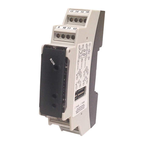
CAN DIN Rail PID Controller
Brand:
Pixsys
| Category:
Controller
| Size: 3.46 MB
Table of Contents
Table of Contents
3
Safety Guidelines
8
Organization of Safety Notices
8
Safety Precautions
8
Precautions for Safe Use
9
Environmental Policy / WEEE
9
Model Identification
10
Technical Data
10
Main Features
10
Hardware Features
10
Software Features
10
Dimensions and Installation
11
Electrical Wirings
11
Wiring Diagram
11
Power Supply
11
Analogue Input
12
Examples of Connection for Volt and Ma Inputs
12
Serial Input
13
CT Input
13
Digital Outputs
13
Analogue Output
13
Leds and Key Function
13
Meaning of Status Lights (LED)
13
Key
13
Dip Switch
14
Controller Functions
14
Loading Default Values
14
Automatic Tuning
14
Manual Tuning
14
Autotuning Launch "Once
14
Synchronized Tuning
15
Automatic/Manual Regulation for % Output Control
15
Heater Break Alarm on CT (Current Transformer)
15
Dual Action Heating-Cooling
16
Soft-Start Function
17
Retransmission Function on Analogue Output
17
LATCH on Function
17
Regulation Control
18
A 0 Time Control
18
B 1 and 3 Burst Fire Control
18
C 2 and 4 Advanced Burst Fire Control
18
Expansion Function
19
Serial Communication
19
Alarm Intervention Modes
19
Absolute Alarm or Threshold Alarm Active over (Index 0X3000 Sub-Index 56 = 1)
19
Absolute Alarm or Threshold Alarm Referred to Command Setpoint Active over (Index 0X3000 Sub-Index 56 = 6)
19
Band Alarm (Index 0X3000 Sub-Index 56 = 3)
19
Upper Deviation Alarm (Index 0X3000 Sub-Index 56 = 4)
20
Lower Deviation Alarm (Index 0X3000 Sub-Index 56 = 5)
20
Canopen
21
SET-UP as Canopen Slave Mode
21
Operation as Canopen Slave Node
21
EDS Files
21
Canopen in Details
22
Object Dictionary
22
Canopen Communication Model
23
Canopen Pre-Defined Connection Set
24
Canopen Identifier Distribution
25
Canopen Boot-Up Process
25
Communication Profile: Start
26
Communication Profile Area
27
Device Type
27
Error Register
28
Pre-Defined Error Field
28
COB-ID SYNC Message
28
Communication Cycle Period
28
Manufacturer Device Name
29
Manufacturer Hardware Version
29
Manufacturer Software Version
29
Node ID
29
Guard Time
29
Life Time Factor
29
Store Parameters
29
Restore Default Parameters
29
COB-ID Emergency Object
30
Inhibit Time Emergency Object
30
Producer Heartbeat Time
30
Identity Object
30
Error Behaviour
30
Receive PDO Communication Parameter
31
Receive PDO Mapping Parameter
32
Transmit PDO Communication Parameter
32
Transmit PDO Mapping
33
Manufacturer Specific Parameter Area
34
Device Specification
34
Command Setpoint
46
Alarm 1 Setpoint
46
Alarm 2 Setpoint
46
Start / Stop Command
46
Heating Output Percentage
46
Cold Output Percentage
46
Cold Junction Temperature
46
Error Flags
46
Real Command Setpoint
47
Digital Outputs Status
47
Command Output Reset
47
Alarms Reset
47
Remote Alarm 1
47
Remote Alarm 2
47
Autotuning Status
47
Automatic/Manual Command
48
Standard Device Profile Area
48
Digital Output
48
Error Mode Output 8Bit
48
Error Value Output 8Bit
49
Analogue Input 16Bit
49
Analogue Output 16Bit
49
Analogue Input Interrupt Trigger Selection
49
Analogue Input Global Interrupt Enable
50
Analogue Input Interrupt Upper Limit Integer
50
Analogue Input Interrupt Lower Limit Integer
50
Analogue Input Interrupt Delta Unsigned
50
Analogue Input Interrupt Negative Delta Unsigned
51
Analogue Input Interrupt Positive Delta Unsigned
51
Analogue Output Error Mode
51
Analogue Output Error Value Integer
51
Error Behaviour
51
PDO Transmission
52
PDO Mapping
52
SYNC Monitoring
52
Node Guarding
52
Heartbeat Monitoring
53
Emergency
53
Norme DI Sicurezza
58
Organizzazione Delle Note DI Sicurezza
58
Note DI Sicurezza
58
Precauzioni Per L'uso Sicuro
59
Tutela Ambientale E Smaltimento Dei Rifiuti / Direttiva WEEE
59
Identificazione del Modello
60
Dati Tecnici
60
Caratteristiche Generali
60
Caratteristiche Hardware
60
Caratteristiche Software
60
Dimensioni Ed Installazione
61
Collegamenti Elettrici
61
Schema DI Collegamento
61
Alimentazione
61
Ingresso Analogico
62
Esempi DI Collegamento Per Ingressi Volt E Ma
62
Ingresso Seriale
63
Ingresso Per Trasformatore Amperometrico
63
Uscite Digitali
63
Uscita Analogica
63
Funzione Dei Led E del Tasto
63
Significato Delle Spie DI Stato (Led)
63
Tasto
64
Dip Switch
64
Funzioni del Regolatore
64
Caricamento Valori DI Default
64
Tuning "Automatico
64
Lancio Dell'autotuning "Manuale
65
Lancio Dell'autotuning "Once
65
Tuning "Sincronizzato
65
Reg. Automatico / Manuale Per Controllo % Uscita
65
Heater Break Alarm Su CT (Trasformatore Amperometrico)
66
Funzionamento in Doppia Azione (Caldo-Freddo)
66
Funzione Soft-Start
67
Funzione Ritrasmissione Su Uscita Analogica
68
Funzione LATCH on
68
Controllo DI Regolazione
69
A 0 Controllo a Tempo
69
B 1 E 3 Burst Fire Control
69
C 2 E 4 Advanced Burst Fire Control
69
Funzione Espansione
69
Comunicazione Seriale
70
Modi D'intervento Allarme
70
Allarme Assoluto O Allarme DI Soglia Attivo Sopra (Index 0X3000 Sub-Index 56 = 1)
70
Allarme Assoluto O Allarme DI Soglia Riferito al Setpoint DI Comando Attivo Sopra (Index 0X3000 Sub-Index 56 = 6)
70
Allarme DI Banda (Index 0X3000 Sub-Index 56 = 3)
70
Allarme DI Deviazione Superiore (Index 0X3000 Sub-Index 56 = 4)
71
Allarme DI Deviazione Inferiore (Index 0X3000 Sub-Index 56 = 5)
71
Canopen
71
SET-UP Nodo Canopen Slave
72
Funzionamento Nodo Canopen Slave
72
EDS Files
72
Canopen Nel Dettaglio
72
Object Dictionary
73
Canopen Communication Model
74
Canopen Pre-Defined Connection Set
75
Canopen Identifier Distribution
76
Procedura DI Boot-Up Canopen
76
Communication Profile: Inizializzazione
77
Communication Profile Area
78
Device Type
78
Error Register
79
Pre-Defined Error Field
79
COB-ID SYNC Message
79
Communication Cycle Period
79
Manufacturer Device Name
79
Manufacturer Hardware Version
80
Manufacturer Software Version
80
Node ID
80
Guard Time
80
Life Time Factor
80
Store Parameters
80
Restore Default Parameters
80
COB-ID Emergency Object
81
Inhibit Time Emergency Object
81
Producer Heartbeat Time
81
Identity Object
81
Error Behaviour
81
Receive PDO Communication Parameter
82
Receive PDO Mapping Parameter
83
Transmit PDO Communication Parameter
83
Transmit PDO Mapping
85
Manufacturer Specific Parameter Area
85
Device Specification
86
Setpoint DI Comando
98
Setpoint Allarme 1
98
Setpoint Allarme 2
98
Comando Start / Stop
98
Percentuale Uscita Caldo
98
Percentuale Uscita Freddo
98
Temperatura Giunto Freddo
98
Flags Errori
98
Setpoint DI Comando Reale
99
Stato Uscite Digitali
99
Riarmo Uscita DI Comando
99
Riarmo Allarmi
99
Allarme 1 Remoto
99
Allarme 2 Remoto
99
Stato Autotuning
100
Comando Automatico / Manuale
100
Standard Device Profile Area
100
Digital Output
101
Error Mode Output 8Bit
101
Error Value Output 8Bit
101
Analogue Input 16Bit
101
Analogue Output 16Bit
102
Analogue Input Interrupt Trigger Selection
102
Analogue Input Global Interrupt Enable
102
Analogue Input Interrupt Upper Limit Integer
103
Analogue Input Interrupt Lower Limit Integer
103
Analogue Input Interrupt Delta Unsigned
103
Analogue Input Interrupt Negative Delta Unsigned
103
Analogue Input Interrupt Positive Delta Unsigned
104
Analogue Output Error Mode
104
Analogue Output Error Value Integer
104
Error Behaviour
104
Trasmissione PDO
104
PDO Mapping
105
Monitoraggio Tramite SYNC
105
Node Guarding
105
Monitoraggio Tramite Heartbeat
105
Emergency
106
Advertisement
Pixsys DRR460 Series User Manual (72 pages)
Brand:
Pixsys
| Category:
Controller
| Size: 2.78 MB
Table of Contents
English
3
Table of Contents
3
Safety Guidelines
5
Organization of Safety Notices
5
Safety Precautions
5
Precautions for Safe Use
6
Environmental Policy / WEEE
6
Model Identification
7
Technical Data
7
Main Features
7
Hardware Features
7
Software Features
7
Dimensions and Installation
8
Electrical Wirings
8
Wiring Diagram
8
Power Supply
8
Analogue Input
9
Examples of Connection for Volt and Ma Inputs
9
Serial Input
9
CT Input
10
Digital Outputs
10
Analogue Output
10
Leds and Key Function
10
Meaning of Status Lights (LED)
10
Key
10
Dip Switch
11
Controller Functions
11
Loading Default Values
11
Controller Start / Stop and Setpoint Modification
11
Automatic Tuning
11
Manual Tuning
11
Autotuning Launch "Once
12
Synchronized Tuning
12
Automatic/Manual Regulation for % Output Control
12
Heater Break Alarm on CT (Current Transformer)
12
Dual Action Heating-Cooling
13
Soft-Start Function
14
Retransmission Function on Analogue Output
14
LATCH on Function
14
Expansion Function
15
Serial Communication
15
Regulation Control
19
A 0 Time Control
19
B 1 and 3 Burst Fire Control
19
C 2 and 4 Advanced Burst Fire Control
20
Table of Configuration Parameters
20
Alarm Intervention Modes
31
Absolute Alarm or Threshold Alarm (Word 2056 = 1)
31
Absolute Alarm or Threshold Alarm Referring to Command Setpoint (Word 2056 = 6)
31
Band Alarm (Word 2056 = 3)
32
Upper Deviation Alarm (Word 2056 = 4)
32
Lower Deviation Alarm (Word 2056 = 5)
32
Table of Anomaly Signals
33
Italian
37
Norme DI Sicurezza
37
Organizzazione Delle Note DI Sicurezza
37
Precauzioni Per L'uso Sicuro
38
Tutela Ambientale E Smaltimento Dei Rifiuti / Direttiva WEEE
38
Identificazione del Modello
39
Dati Tecnici
39
Caratteristiche Generali
39
Caratteristiche Hardware
39
Caratteristiche Software
39
Dimensioni Ed Installazione
40
Collegamenti Elettrici
40
Schema DI Collegamento
40
Alimentazione
40
Ingresso Analogico
41
Esempi DI Collegamento Per Ingressi Volt E Ma
41
Ingresso Seriale
41
Ingresso Per Trasformatore Amperometrico
42
Uscite Digitali
42
Uscita Analogica
42
Funzione Dei Led E del Tasto
42
Significato Delle Spie DI Stato (Led)
42
Tasto
42
Dip Switch
43
Funzioni del Regolatore
43
Caricamento Valori DI Default
43
Start / Stop del Regolatore E Modifica Setpoint
43
Tuning "Automatico
43
Lancio Dell'autotuning "Manuale
43
Lancio Dell'autotuning "Once
44
Tuning "Sincronizzato
44
Regolazione Automatico / Manuale Per Controllo % Uscita
44
Heater Break Alarm Su CT(Trasformatore Amperometrico)
44
Funzionamento in Doppia Azione (Caldo-Freddo)
45
Funzione Soft-Start
46
Funzione Ritrasmissione Su Uscita Analogica
46
Funzione LATCH on
46
Funzione Espansione
47
Comunicazione Seriale
47
Controllo DI Regolazione
52
A 0 Controllo a Tempo
52
B 1 E 3 Burst Fire Control
52
C 2 E 4 Advanced Burst Fire Control
52
Tabella Parametri DI Configurazione
53
Modi D'intervento Allarme
64
Allarme Assoluto O Allarme DI Soglia Attivo Sopra (Word 2056 = 1)
64
Allarme DI Banda (Word 2056 = 3)
64
Allarme DI Deviazione Superiore (Word 2056 = 4)
65
Allarme DI Deviazione Inferiore (Word 2056 = 5)
65
Tabella Segnalazioni Anomalie
65
Advertisement
Related Products
Pixsys DRR450
Pixsys DRR 245
Pixsys DRR244
Pixsys DRR460-12A-T128
Pixsys DRR460-12A-CAN
Pixsys DRR245-21-ABC-T
Pixsys DRR227
Pixsys DRR224
Pixsys DRR224-12ABC
Pixsys DRR227-12ABC
Pixsys Categories
Controller
Measuring Instruments
Media Converter
Touch Panel
Touchscreen
More Pixsys Manuals
Login
Sign In
OR
Sign in with Facebook
Sign in with Google
Upload manual
Upload from disk
Upload from URL