Sign In
Upload
Manuals
Brands
Pioneer Manuals
Flat Panel TV
ARP3476
Pioneer ARP3476 Manuals
Manuals and User Guides for Pioneer ARP3476. We have
1
Pioneer ARP3476 manual available for free PDF download: Service Manual
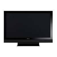
Pioneer ARP3476 Service Manual (202 pages)
Brand:
Pioneer
| Category:
Flat Panel TV
| Size: 16.67 MB
Table of Contents
Safety Information
2
Important Check Points for Good Servicing
4
Table of Contents
5
1 Service Precautions
6
Notes on Soldering
6
Charged Section and High Voltage Generating Point
7
2 Specifications
8
Accessories
8
Speaker Accessories
9
Specifications
10
Dimensions
11
Panel Facilities
12
Front Section
12
Command Side of the Panel
12
Rear Section
13
Remote Control Unit
14
3 Basic Items for Service
16
Check Points after Servicing
16
Items to be Checked after Repair
16
Cleaning
16
Quick Reference
17
Notes, PD/SD Diagnosis, and Methods for Various Settings
17
Mode Transition and Structure of Layers in Service Factory Mode
18
PCB Locations
19
List of Assemblies
19
Jigs List
20
4 Block Diagram
22
Overall Wiring Diagram (1/2)
22
Overall Wiring Diagram (2/2)
24
Overall Block Diagram (1/2)
26
Overall Block Diagram (2/2)
28
Power Supply Unit
30
50F X Drive Assy
32
50F y Drive, 50F Scan a and B Assys
33
Power Supply Block of 50F X, y Drive, 50F Scan a and B Assys
34
50F Address L and S Assys
35
50F Digital Assy
36
Main Assy (Dtv Block Diagram)
37
Power Supply Block of Main Assy
38
IO Audio Assy
40
LED and IR Assys
42
5 Diagnosis
43
Power Supply Operation
43
LED Display Information
43
Power on Sequence
44
Details of Power on Sequence
45
AC-OFF Main Power OFF, Passive Standby
45
AC-ON Main Power OFF, Passive Standby
45
AC-ON Main Power OFF, Active Standby
46
AC-ON Main Power ON, Passive Standby
46
AC-ON Main Power ON, Active Standby
47
AC-ON Main Power ON, Function Standby
47
AC-ON Main Power ON, PDP Screen on
48
Diagnosis Flowchart of Failure Analysis
49
Whole Unit
49
Drive Assy
52
Diagrammatic View of the y DRIVE Assy
55
Diagrammatic View of the X DRIVE Assy
55
Digital Assy
57
Flowchart of Failure Analysis for the Video System
59
Video System
60
Details on How to Confirm the Factory DTV Tuning Status
65
Home Media Gallery
66
How to Enter DTB Service Menu
67
Audio System
68
Block Diagram of the Power-Down Signal
72
Diagnosis of Pd (Power-Down)
72
PD Diagnosis of Failure Analysis
74
Block Diagram of the Shutdown Signal
76
Diagnosis of Sd (Shutdown)
76
SD Diagnosis
78
Non-Failure Information
80
Information on Symptoms that Do Not Constitute Failure
80
Function of Decreasing the Brightness Level
81
Limiting for the Maximum Number of SUS Pulses
81
ABL Adjustment Value Offset
81
Relationship between Input APL and Number of SUS Pulses
81
Outline of the Operation
82
Panel Drive-Power On/Off Function
82
When the Panel Drive-Power Is ON/OFF
82
Specification of the Fan Control
83
Operation Specifications
83
Processing in Abnormality
84
Speaker Short-Circuit
84
Circuit Configuration
84
Specifications for Port Monitoring
84
Power Supply and DC-DC Converter
85
Fan and Temperature Sensor
86
Outline of RS-232C Command
87
Prepared Tools
87
List of RS-232C Commands
88
Details of each Commands
97
QS1 (Panel Status)
97
QS2 (Panel Operation Data)
98
QS3 (Other Data on the Panel)
99
QS5 (Color Sensor Data)
99
QSP (Sub Version of the Panel Section)
100
QAJ (Panel Adjustment Data)
101
QPW (Video Adjustment Data of the Panel)
102
QPF (Function of the Panel)
103
QPM (Pulse Meter Value)
103
QPD (Power down Logs)
104
QSD (Shutdown Logs of the Panel Section)
105
QSE (Destination Peculiar Information)
106
QMT (Status Information of MTB/MR Section)
106
QNG (Shutdown Information of MTB Section)
107
QSI (Input Signal Data)
109
DRV (Panel Drive-Power On/Off)
110
FAY/FAN (Adjustment Commands Permission/Prohibition)
110
FAJ/UAJ/CBU/BCP (Backup Function for Adjustment Value)
110
6 Service Factory Mode
111
Outline of the Service Factory Mode
111
Service Factory Mode Transition Chart
111
How to Enter/Exit Service Factory Mode
111
Functions When Entering the Service Factory Mode
112
Fuctions Whose Setting Are Set to off
112
User Data
112
Remote Control Code in Service Factory Mode
113
PDP Service Remote Control
114
Factory Hierarchical Table
115
Indications in Service Factory Mode
117
Main-Item Indications
117
Details of Factory Menu
119
Information
119
Main NG
121
MTB Side's Shutdown NG Information
121
Clear the MAIN NG History
122
Temperature
123
Hour Meter
124
HDMI Signal Info
125
VDEC Signal Info
127
Panel Factory
128
Operation Items
128
Details of Indications in each Layer
129
Panel Information
129
Panel Works
129
Power down
130
Shut down
131
Panel-1 ADJ
132
Panel-2 ADJ
134
Panel Function
135
Etc
136
Raster Mask Setup
137
Pattern Mask Setup
138
Combi Mask Setup
139
Option
140
Initialize
141
Side Mask Level
141
Final Setup
142
DTB Service Menu
143
Wide XGA Auto
143
Auto Adjustment
143
Digital Tuner Service Menu
144
Remote Control Code in Digital Tuner Service Menu
144
Hierarchical Table of Digital Tuner Service Menu
144
Digital Tuner Service Menu Screen
144
Home Media Gallery Screen
145
Digital Screen
145
Software Version Screen
145
7 Disassembly
146
Flowchart of Removal Order
146
Speaker System
147
Disassembly
147
Rear Case
148
Side Input Shield
149
Under Cover
149
T Panel U Assy
150
Notes on Lead Dressing
151
Access to 50F DIGITAL Assy
152
Front Bezel
153
Access to ADDRESS L and S Assys
154
Access to SCAN a and B Assys
156
Precautions for Speaker System
157
8 Each Setting and Adjustment
158
Adjustment Required When the Unit Is Repaired or Replaced
158
When any of the Following Assemblies Is Replaced
158
When any of the Following Assemblies Is Repaired
159
Outline
161
Backed up Data
161
How to Copy Backup Data
161
Backup of the Eeprom (Digital Assy)
161
How to Clear History Data
164
Clearance of Various Logs after the Assys Are Replaced
164
Adjustment When the Service Panel Assy Is Replaced
165
Example of the On-Screen Display During Panel Factory Mode
165
Overview
166
Preparation before Adjustment
167
Main Flowchart Checking VOL OFFSET
168
Checking VOL YNOFSA D
169
Recovery Flowchart Changing the VOL OFFSET Setting
170
Changing the VOL OFFSET Setting
171
Adjustment When the Drive Assys Are Replaced
176
Time Lag Adjustment of the Control Signal
176
Delay Adjustment of the Control Signal
177
SUS-B Adjustment
178
SUS-D Adjustment
178
How to Update USB
179
Preparation
179
Description of the Figures
179
Procedures
179
List of Frequency of LED Flashing When Updating Fails
180
Adjustment When the Main or IO Audio Assy Is Replaced
181
Explanation
181
Adjustment Procedure
181
9 Exploded Views and Parts List
182
Packing Section
182
Packing Section Parts List
183
Rear Section
184
Front Section
186
Chassis Section (1/2)
188
Chassis Section (2/2)
190
Panel Chassis Section
192
Multibase Section
194
PDP Service Assy
196
Exterior Section
196
Table Top Stand
198
Speaker System (Packing)
199
Speaker System
200
Baffle
201
CS Assy Parts List
201
Advertisement
Advertisement
Related Products
Pioneer ARP2311
Pioneer ARP-230-0
Pioneer ARP3184
Pioneer ARP3356
Pioneer ARP3357
Pioneer ARP3393
Pioneer ARP-006-O
Pioneer ARP3204
Pioneer ARP3187
Pioneer AVIC-Z830DAB
Pioneer Categories
Car Receiver
Receiver
Stereo Receiver
Amplifier
DVD Player
More Pioneer Manuals
Login
Sign In
OR
Sign in with Facebook
Sign in with Google
Upload manual
Upload from disk
Upload from URL