Sign In
Upload
Manuals
Brands
Phoenix Contact Manuals
Transceiver
RAD IFS Series
Phoenix Contact RAD IFS Series Manuals
Manuals and User Guides for Phoenix Contact RAD IFS Series. We have
1
Phoenix Contact RAD IFS Series manual available for free PDF download: User Manual
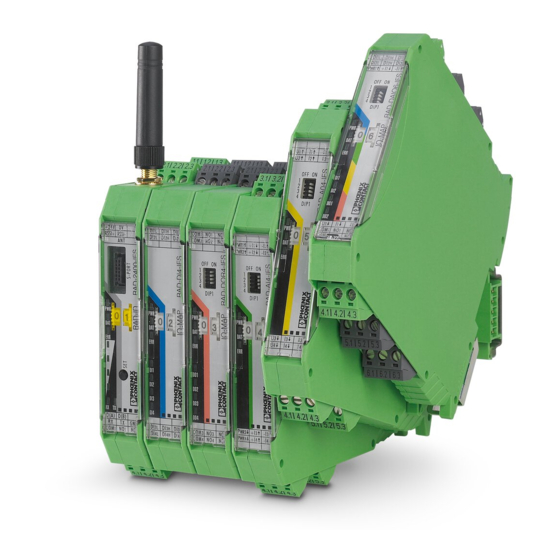
Phoenix Contact RAD IFS Series User Manual (198 pages)
Radioline - Wireless transmission system for serial interfaces and I/O signals
Brand:
Phoenix Contact
| Category:
Transceiver
| Size: 15 MB
Table of Contents
Table of Contents
3
1 For Your Safety
7
Marking of Warning Notes
7
Qualification of Users
7
Field of Application of the Product
8
Installation Notes
10
Installation in Zone 2
11
Notes for Individual I/O Extension Modules
12
UL Notes (RAD-2400-IFS and I/O Extension Modules Only)
12
FCC, Industry Canada, IFT Mexico (RAD-2400-IFS Only)
13
2 Brief Description
15
Wireless Modules
15
Firmware Versions
16
I/O Extension Modules
17
Application Examples
18
3 Installation
19
Wireless Module Structure
19
Basic Circuit Diagram
20
Mounting and Removal
20
Connecting the Cables
22
Connecting the Power Supply
23
Serial Interfaces
24
Connecting the Antenna
27
4 Configuration and Startup
29
Default Settings of the Wireless Module
29
Operating Mode of the Wireless Module
31
Setting the Address of the Wireless Module Using the Thumbwheel
35
Configuration Using the Configuration Stick
35
Copying the Device Settings Via a Memory Stick
37
Configuration Via the PSI-CONF Software
38
Diagnostics on the Wireless Module
44
Diagnostics Via PSI-CONF Software
49
Starting up I/O Extension Modules
52
Startup Time of the Wireless Station
54
5 Serial Data Mode
55
Frame-Based Data Transmission
57
Setting Telegram Pauses Based on the Example of Modbus/Rtu
58
6 PLC / Modbus/Rtu
59
PLC / Modbus/Rtu Mode
59
PLC / Modbus/Rtu Dual Mode
62
Watchdog
65
Modbus Function Codes
66
Module Type and Error Code Registers for I/O Extension Modules
67
Modbus Memory Map
68
Error Codes and Formats for Analog Input and Output Values
83
Radioline Function Blocks
84
7 Description of I/O Extension Modules
87
RAD-AI4-IFS - Analog Extension Module with Four Inputs
87
RAD-PT100-4-IFS - Extension Module with Four Temperature Inputs
91
RAD-AO4-IFS - Analog Extension Module with Four Outputs
98
RAD-DI4-IFS - Digital Extension Module with Four Inputs
102
Figure 7-18 RAD-DI4-IFS Structure
103
Figure 7-19 Basic Circuit Diagram for the RAD-DI4-IFS
103
Figure 7-20 Diagnostic Leds of the RAD-DI4-IFS
104
RAD-DI8-IFS - Digital Extension Module with Eight Inputs
106
Figure 7-21 RAD-DI8-IFS Structure
106
Figure 7-22 Basic Circuit Diagram for the RAD-DI8-IFS
107
Figure 7-23 DIP Switches of the RAD-DI8-IFS
107
Figure 7-24 Diagnostic Leds of the RAD-DI8-IFS
109
RAD-DOR4-IFS - Digital Extension Module with Four Outputs
111
Figure 7-25 RAD-DOR4-IFS Structure
111
Figure 7-26 Basic Circuit Diagram for the RAD-DOR4-IFS
112
Figure 7-27 DIP Switches of the RAD-DOR4-IFS
112
Figure 7-28: Diagnostic Leds of the RAD-DOR4-IFS
113
RAD-DO8-IFS - Digital Extension Module with Eight Outputs
115
Figure 7-29 RAD-DO8-IFS Structure
116
Figure 7-30 Basic Circuit Diagram for the RAD-DO8-IFS
117
Figure 7-31 DIP Switches of the RAD-DO8-IFS
117
Figure 7-32 Diagnostics Leds of the RAD-DO8-IFS
118
RAD-DAIO6-IFS - Analog/Digital Extension Module with Six Channels
120
Figure 7-33 RAD-DAIO6-IFS Structure
121
Figure 7-34 Basic Circuit Diagram for the RAD-DAIO6-IFS
122
Figure 7-35 DIP Switches of the RAD-DAIO6-IFS
122
Figure 7-36 Diagnostics Leds of the RAD-DAIO6-IFS
123
8 Planning Wireless Systems
125
Delay Time
125
Pulse Transmission
127
Trusted Wireless 2.0
127
Figure 8-1 Penetration of Obstacles at Different Frequencies
129
Figure 8-2: Point-To-Point Connection, Star Network, Self-Healing Mesh Network
130
Figure 8-3: Distributed Network Management with Parent-Child Zones
130
RF Bands
131
Figure 8-4: RF Bands in the 2.4 Ghz Wireless System
131
Figure 8-5: RF Bands in the 868 Mhz Wireless System
131
Planning Wireless Paths
132
Practical Test
132
Selecting Antenna Cables and Antennas
133
Installing Antennas
134
Figure 8-6 Antenna Polarization
134
Figure 8-7: Decoupling of Wireless Paths Due to Directivity and Different Polarization Levels
135
Figure 8-8 Outdoor Installation of Antennas
136
Level and Attenuation of Wireless Modules and Accessories
137
Free Space Attenuation
139
Propagation of Radio Waves
141
Figure 8-9 Dispersion on a Rough Surface
141
Figure 8-10 Diffraction on an Edge
141
Figure 8-11 Reflection on a Metal Surface
141
Figure 8-12 Reduction of Radio Waves When Penetrating a Wall
142
Figure 8-13 Angle of the Transmitter and Receiver
143
Figure 8-14 Radio Dead Spot
143
Fresnel Zone
144
Figure 8-15 Wireless Path with Strong Wind
144
Figure 8-16 Fresnel Zone
145
Range
146
Equivalent Isotropically Radiated Power (EIRP)
147
System Calculation in Free Space
148
Figure 8-17 Free Space Attenuation
148
Practical Examples
149
Figure 8-18 Bush with an Attenuation of Approximately 15 Db
149
Figure 8-19 Forest with an Attenuation of Around 40 Db
149
9 Detecting and Removing Errors
151
Loopback Test During Serial Data Transmission
157
Figure 9-1 Loopback Test on an RS-232 Interface
158
Figure 9-2 Settings in Hyperterminal
158
10 Technical Data for the Wireless Modules
159
A Technical Appendix
171
Typical Combinations of Antennas and Adapter Cables
171
Figure A-1 Omnidirectional Antenna, 2 Dbi
171
Figure A-2: Omnidirectional Antenna with Protection against Vandalism, 3 Dbi
172
Figure A-3: Omnidirectional Antenna, 2.5 Dbi
173
Figure A-4: Omnidirectional Antenna, 6 Dbi, Without Surge Protection
174
Figure A-5: Omnidirectional Antenna, 6 Dbi, with Surge Protection
175
Figure A-6: Directional Antenna, 9 Dbi, with Outdoor Surge Protection
176
Figure A-7: Parabolic Antenna, 19 Dbi, with Outdoor Surge Protection
177
Figure A-8: Omnidirectional Antenna, 4 Dbi, with Surge Protection
178
Figure A-9: Directional Antenna, with Surge Protection
179
Figure A-10: Directional Antennas, 8 Dbi, with 2-Way Outdoor Antenna Splitter
181
Figure A-11: Antenna Installation in Zone 2
182
A 2 Control Box for Wireless Systems
184
Figure A-12: Control Box with Wireless System
184
Appendixes
185
B 1 List of Figures
185
Table of Contents
187
B 2 List of Tables
189
B 3 Index
191
Advertisement
Advertisement
Related Products
Phoenix Contact RAD-80211-XD
Phoenix Contact RAD-80211-XD-WM
Phoenix Contact RAD-80211-XD-BUS
Phoenix Contact RAD-900-IFS
Phoenix Contact RAD-AI4-IFS
Phoenix Contact RAD-PT100-4-IFS
Phoenix Contact RAD-DI4-IFS
Phoenix Contact RAD-DI8-IFS
Phoenix Contact RAD-DO8-IFS
Phoenix Contact RAD-DAIO6-IFS
Phoenix Contact Categories
Controller
Switch
Control Unit
Power Supply
Media Converter
More Phoenix Contact Manuals
Login
Sign In
OR
Sign in with Facebook
Sign in with Google
Upload manual
Upload from disk
Upload from URL