Sign In
Upload
Manuals
Brands
Phoenix Contact Manuals
Touch Panel
HTP10 1000
Phoenix Contact HTP10 1000 Manuals
Manuals and User Guides for Phoenix Contact HTP10 1000. We have
2
Phoenix Contact HTP10 1000 manuals available for free PDF download: User Manual
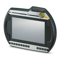
Phoenix Contact HTP10 1000 User Manual (110 pages)
Mobile Touch Panel with TFT-Display
Brand:
Phoenix Contact
| Category:
Touch Panel
| Size: 2 MB
Table of Contents
Table of Contents
3
1 Introduction
7
Purpose of the Document
7
Preconditions
7
Intended Use
9
Notes on this Document
10
Contents of Document
10
Not Contained in this Document
10
Documentation for Further Reading
10
Information about MD 2006/42/EC
11
Quantitative Safety Relevant Specifications for Emergency Stop-Button and Enabling Control Device
11
Change of Terminology
11
Relationship between Performance Level and Safety Integrity Level
12
Abbreviations
12
2 For Your Safety
15
Labeling of Warning Notes
15
General Safety Instructions
16
Personnel Safety Instructions
18
Transport Conditions
18
3 Description of the Handheld Terminal
19
Front View
20
Rear View
21
Side View
22
Handling the HTP10 1000
22
Type Plate
23
4 Display an Operating Elements
25
Membrane Keypad
25
Membrane Keypad Front Side
25
Touchscreen
26
5 Connections and Wiring
27
Cable Entrance Area
27
Cable Routing in Cable Entrance Area
27
Cable Entrance Area HTP10 1000
27
Installing the Connection Cable
28
Tools Required
29
Cable Installation
29
Power Supply
31
Connection of the HTP10 1000 to a Control
32
Connection of the Cable Shield in a Control Cabinet
32
Emergency Stop Button
33
Grey Stop Button
33
Illuminated Emergency Stop
34
Device for Approval Control with Internal Evaluation Electronics
34
Requirements for Enabling Control Device Outputs and Electronics
35
Functionality
35
Enabling Control Electronics - Monitoring on Short Circuits and Shunt Currents
35
Switch Positions
35
Switch Position
35
Contact Travel Diagram for Normal Operation
36
Contact Travel Diagram for Panic Operation
36
Connection Example with Monitoring Device (PILZ PNOZ S3)
38
Connection Example for HTP10 1000 to PILZ PNOZ S3 Monitoring Device
38
Foreseeable Misuse of the Device for the Approval Control (Permission Button)
39
Device for Approval Control Without Internal Evaluation Electronics
39
Functioning
40
Contact Travel Diagram for Enabling
40
Contact Travel Diagram for Panic
41
Example of Connection with Control Relay (PILZ PNOZ S6.1)
42
Foreseeable Misuse of the Device for the Approval Control (Permission Button)
43
Ethernet
43
Pin Assignment
44
USB Port
44
6 Operating Behavior
45
Start-Up
45
Cockpit Startup Phase
45
Cockpit Functions
46
Settings and Functions
47
Default Values of Cockpit
49
Portico and Profinet
50
Configure Portico
50
Portico Client Manager - New Connection
50
Portico Client Manager - Connection Settings
50
Portico Client Manager - Connection
50
Units Screen
51
Units Screen - Units Configured
51
Units Screen - Units Active
52
Shut down the HTP10 1000
53
HTP10 1000 in Combination with the Connection Box HTP10 1000 CB
53
7 Configuration
55
8 Maintenance
57
Cleaning the Touch Screen
57
Creating a Backup
58
Select "Emmc
58
Restore a Backup / Software Update
60
9 Disposal
63
Disposal of the Module
63
Disposal of the Battery
63
10 Technical Data
65
In General
65
Environmental Conditions
65
Processor
65
Interfaces
66
E-Stop Button / Gray Stop-Switch
66
Enabling Control Device
66
Mechanical Properties
67
Dimensions, Weight
67
11 Options
69
Illuminated Emergency Stop Button
69
Two Enable Switches
69
Internal Enabling Control Electronics
69
12 Accessories
71
Wall Holders HTP10 1000 WH
71
Dimensional Drawings
72
Hanging the Handheld Terminal on the Wall Holder
73
Touch Stylus Holder
73
Connection Box HTP10 1000 CB
74
Views and Basic Dimensions
74
Connection Cable HTP10 1000 CC XX
74
Connection Cable HTP10 1000 CC XX
76
13 EC Directives, Standards and Regulations
79
EC Directives
79
Standards
79
Regulations
81
A Machinery Safety
83
A 1 Hazard and Risk Analysis
84
A 2 Principles for the Integration
84
A 3 Technical Construction File
84
A 4 State of the Art
85
A 5 Recognition of Conformity by Means of Harmonized Standards
85
Selection of Performance Level and Safety Categories in Accordance with en ISO 13849-1
85
A 7 Application of Handheld Terminals in Special Operating Modes
87
A 8 Information about the Emergency Stop Button
88
Appendix A
88
Emergency Stop Button (Not Activated) / Emergency Stop Button Pressed
88
A 9 Manual Control of Machines in Special Operating Modes
89
A 10 Information about Enabling Control Devices
90
B Electromagnetic Compatibility
93
The Electromagnetic Environment - Interference Sources, Interference Sinks and Coupling Paths
93
B 2 EMC Measures on HTP10 1000
96
Appendix B
97
Insufficient Contacting of a Cable Shield
97
Separation of the Control Signals and the Data Line Signals
97
C Chemical Resistance
99
Appendixes
103
List of Figures
103
D 2 List of Tables
107
Index
107
Advertisement
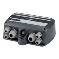
Phoenix Contact HTP10 1000 User Manual (62 pages)
Connection Box for Mobile Touch Panel
Brand:
Phoenix Contact
| Category:
Accessories
| Size: 0 MB
Table of Contents
Table of Contents
3
Introduction
7
Purpose of the Document
7
Preconditions
7
Intended Use
9
Notes on this Document
10
Contents of Document
10
Documentation for Further Reading
10
Information about MD 2006/42/EC
10
Quantitative Safety Relevant Specifications for Emergency Stop-Button and Enabling Control Device
11
Relationship between Performance Level and Safety Integrity Level
11
Abbreviations
12
Emergency Stop Switch
12
Safety Notes
13
Labeling of Warning Notes
13
General Safety Instructions
13
Personnel Safety Instructions
14
ESD Information
16
Description of the Module
17
Front View
18
Rear View
19
Bottom
19
Top
20
Type Plate
20
Displays and Operating Elements
21
Power LED
21
Illuminated Emergency Stop LED (Illuminated E-Stop Only)
21
Ethernet Status Leds
21
Status LED Bar
22
Mounting and Installation Instructions
23
Drilling Template for Wall Mounting
23
Installing the Connection Box
23
Connections and Wiring
25
Wiring up the Connection Box
26
Terminal Strip S16
27
Power Supply
27
Pin Assignment
28
Terminal Strip S10
29
Pin Assignment
29
Ethernet
30
Pin Assignment
30
Changes to the Wiring
31
Closing the Connection Box
32
Configuration
33
Box ID Configuration
34
Brightnessof Illuminated Emergency Stop
35
Validating the Connection Box
37
Operation and Handling
39
Operating States
39
Operating Behavior
40
10 Diagnosis
41
11 Maintenance
43
12 Disposal
45
Disposalof the Module
45
13 Technical Data
47
In General
47
Power Supply
47
Ambient Conditions
47
Interfaces
47
Emergency Stop Functions on the Connection Box
48
Dimensions, Weight
48
14 Options
49
Emergency Stop Button
49
Technical Data
49
Key-Operated Switch
49
15 EC Directives, Standards and Regulations
51
EC Directives
51
Standards
51
Regulations
53
Appendixes
55
List of Figures
55
List of Tables
57
Index
59
Advertisement
Related Products
Phoenix Contact GW PL HART8-BUS
Phoenix Contact GW PL HART4-R-BUS
Phoenix Contact GW PL HART8-R-BUS
Phoenix Contact GW PL HART8+AI-BUS
Phoenix Contact GW PL HART4-BUS
Phoenix Contact ELR H5-IES-SC-24DC/500AC-0,6
Phoenix Contact ELR H5-IES-SC-230AC/500AC-0,6
Phoenix Contact ELR H5-IES-SC-24DC/500AC-2
Phoenix Contact ELR H5-IES-SC-230AC/500AC-2
Phoenix Contact ELR H5-IES-SC-24DC/500AC-9
Phoenix Contact Categories
Controller
Switch
Power Supply
Control Unit
Industrial Equipment
More Phoenix Contact Manuals
Login
Sign In
OR
Sign in with Facebook
Sign in with Google
Upload manual
Upload from disk
Upload from URL