Sign In
Upload
Manuals
Brands
Phoenix Contact Manuals
Controller
CONTACTRON CSS 1.5-1/3-EMC
Phoenix Contact CONTACTRON CSS 1.5-1/3-EMC Manuals
Manuals and User Guides for Phoenix Contact CONTACTRON CSS 1.5-1/3-EMC. We have
1
Phoenix Contact CONTACTRON CSS 1.5-1/3-EMC manual available for free PDF download: User Manual
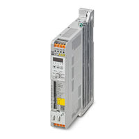
Phoenix Contact CONTACTRON CSS 1.5-1/3-EMC User Manual (148 pages)
Speed Starter
Brand:
Phoenix Contact
| Category:
Controller
| Size: 37 MB
Table of Contents
Table of Contents
5
Qualification of Users
9
For Your Safety
9
Labeling of Warning Notes
9
Product Changes
10
After Unpacking
10
Field of Application of the Product
10
Foreseeable Misuse
10
Intended Use
10
Safety Notes
11
Reverse Running
13
Model Overview
15
Introduction
15
Nameplate Information (Example)
16
Model Name
17
Dimensions
19
Frame A1
19
Frame A1: CSS 0.25-1/3, CSS 0.25-3/3, CSS
19
Dimensions Frame A1 (Unit: MM [Inch])
19
Dimensions Frame A2 (Unit: MM [Inch])
20
Frame A2
20
Frame A2: CSS 0.25-1/3-EMC, CSS 0.25-3/3-EMC
20
Frame B1 with Fan
21
Frame B1 with Fan (Unit: MM [Inch])
21
Frame B1 with Heat Sink
22
Frame B1 with Heat Sink (Unit: MM [Inch])
22
Frame B2
23
Frame B2: CSS 0.55-1/3-EMC, CSS 0.75-1/3-EMC, CSS 1.5-1/3-EMC, CSS 1.5-3/3-EMC
23
Installation
25
Mounting Clearances
25
Airflow Side-By-Side Horizontal Installation / Zero Stacking Installation / Side-Mounting Installation
26
Side-Mounting Installation
26
Derating Curve
27
DIN Rail Mounting
29
Installing the CONTACTRON Speed Starter Onto the DIN Rail
29
Removing the CONTACTRON Speed Starter from the DIN Rail
30
Wiring
31
Power Terminals
31
Control Terminals
32
Wiring Precautions
33
PE Terminal
34
Wiring Diagram
35
Connection Possibilities
36
Input: 1-Phase Power
36
Input: 3-Phase Power
37
Jumper
38
Removal
39
Mains Types
41
No Stable Neutral Grounding in a Three -Phase Autotransformer Configuration
43
Motor Cable Length
44
Consequence of Leakage Current
44
Consequence of the Surge Voltage
44
Maximum Motor Cable Length at 4 Khz Carrier Frequency (1-Phase)
44
Maximum Motor Cable Lenght at 4 Khz Carrier Frequency (3-Phase)
45
Input: 3-Phase Power
47
Main Circuit Diagram
47
Standard Fuses an Circuit Breakers
49
Standard Fuses (for IEC)
49
Css 0.75-3/3-Emc
49
Standard Fuses and Circuit Breakers (for UL and Cul)
50
Branch Circuit Protection with Standard Fuses
50
Standard Fuses with SCCR (UL and Cul)
50
Branch Circuit Protection with Circuit Breakers
52
Circuit Breakers with SCCR (UL and Cul)
52
Accessories and Spare Parts
53
EMC Shielding Plate
53
Installation
55
Fan Kit
58
Fan Kit EM-CSS-FAN-35 (Art.-No. 1276911)
59
Fan Kit EM-CSS-FAN-45 (Art.-No. 1276912)
59
Fan Removal
60
Fan Installation
60
Status Display
61
Control Panel
61
Panel
61
Control Panel Operation Process
63
Rotary Switch in "CURRENT" Position
63
Rotary Switch in "RAMP" Position
64
Rotary Switch in "STATUS" Position
65
Rotary Switch in "SPEED1" / "SPEED2" Position When STOP
66
Rotary Switch in "SPEED1" / "SPEED2" When RUNNING
67
Rotary Switch in "SPEED1" or "SPEED2" Position for Direction Setting at STOP
68
Rotary Switch in "OPTIONS" Position
69
1-Phase Device
70
Status Summary
72
10 Description of Parameter Settings
73
Rotary Switch in "CURRENT" Position
73
Rotary Switch in "RAMP" Position
74
Rotary Switch in "STATUS" Position
75
SPEED2 Direction
76
SPEED2 Frequency Command
76
SPEED1 Direction
76
SPEED1 Frequency Command
76
Rotary Switch in "SPEED1" or "SPEED2" Position
76
Rotary Switch in "OPTIONS" Position
77
Motor Rated Frequency
77
Motor Rated Voltage
78
Highest Output Frequency
78
Pulse Frequency
79
Voltage Lift
81
Start Boost
81
V/F-Waveform
81
Slip Compensation
82
Ptc
83
10.5.10 Parameter Lock
84
10.5.11 Parameter Reset
84
10.5.12 Identity Code
85
10.5.13 Firmware Version
85
10.5.14 Relay Output
85
11 Warning Codes
87
12 Error Codes
91
13 STO - Safe Torque off
103
Defined Safety Function
103
Safety Information
104
STO Input
104
Safety Parameters
105
Safety Parameters for en ISO 13849-1
105
Safety Parameters for IEC 61508, Part 1-7 and IEC/EN 62061 - High Demand
105
14 Application Notes
107
Application Examples Without STO Function
107
1-Phase
107
3-Phase
108
Application Examples with STO Function
109
Block Diagram
112
1-Phase
112
3-Phase
113
A 1 230 V Models
115
A Technical Data
115
A 2 480 V Models
119
A 3 General Specifications
123
Environment for Operation, Storage and Transportation
125
A 5 Derating for Altitude and Carrier Frequency
127
Rated Output Current [%] of 230 V Models for Different Carrier Frequencies
128
Operational Limits
129
Rated Output Current [%] of 480 V Models for Different Carrier F
129
A 6 Operational Limits
129
A 7 Applicable Standards
130
B Reference Table for the Seven-Segment Digital Control Panel LED Display
131
Reference Table for the Seven-Segment Digital Control Panel LED Display
131
C Appendixes
133
Appendixes
133
List of Figures
133
List of Tables
137
Explanation of Terms
139
Index
141
Advertisement
Advertisement
Related Products
Phoenix Contact CONTACTRON CSS 1.5-3/3-EMC
Phoenix Contact 1201135
Phoenix Contact 1201511
Phoenix Contact 1201679
Phoenix Contact 1201683
Phoenix Contact 1201695
Phoenix Contact 1201713
Phoenix Contact 1201829
Phoenix Contact 1276904
Phoenix Contact 1624130
Phoenix Contact Categories
Controller
Switch
Power Supply
Control Unit
Industrial Equipment
More Phoenix Contact Manuals
Login
Sign In
OR
Sign in with Facebook
Sign in with Google
Upload manual
Upload from disk
Upload from URL