Sign In
Upload
Manuals
Brands
PG Drives Technology Manuals
Controller
SK79649-01
PG Drives Technology SK79649-01 Manuals
Manuals and User Guides for PG Drives Technology SK79649-01. We have
1
PG Drives Technology SK79649-01 manual available for free PDF download: Technical Manual
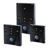
PG Drives Technology SK79649-01 Technical Manual (72 pages)
Brand:
PG Drives Technology
| Category:
Controller
| Size: 3 MB
Table of Contents
Table of Contents
3
About this Manual
6
Icons
6
Chapter 1 - Installation
7
Introduction
9
Guidelines for Working on Electric Vehicles
9
Precautions for Working on Electric Vehicles
9
Uncontrolled Operation
9
High Current Arcs
9
Lead Acid Batteries
9
Precautions for Use
9
Frame Dimensions
10
Small Frame
11
Medium Frame
12
Large Frame
13
Mounting
14
Cable Routing
14
Wiring Guidance
15
Battery and Motor Connections
16
Tightening Torque for Battery and Motor Connections
16
Battery and Motor Wire Size and Type Selection
17
Battery and Motor Connection Crimps and Tooling
17
Control Connections
17
Control Connection Wiring
17
Control Connections Crimps and Tooling
18
Connections
18
Battery Connection
18
Power Fuse
18
Line Contactor & Pre-Charge Resistor
18
Discharge Resistor
18
6.1.4 Emergency Disconnect Switch
18
Motor Connections
19
Control Connections
19
Connector 'A' - Vehicle Interface (16-Way)
19
Pin 1 - Forward Switch
19
Pin 2 - Reverse Switch
19
Pin 3 - Footswitch / Belly Button
19
Pin 4 - Seat / Tiller
19
Pin 5 - Speed Limit 1 / Inch Forward
19
Pin 6 - Speed Limit 2 / Inch Reverse
20
Pin 7 - Speed Limit 3 / Handbrake
20
Pin 8 - Accelerator / Footbrake
20
Pin 9 - Accelerator / Footbrake
20
Pin 10 - Keyswitch
21
Pin 11 - Contactor Coil Supply
21
Pin 12 - Line Contactor
21
Pin 13 - Electric Brake Contactor
21
Pin 14 - Power Steer Contactor
21
Pin 15 - +12V Supply
21
Pin 16 - +5V Potentiometer Supply
21
Connector 'B' - Communications (8-Way)
21
Pin 1 - Not Used
21
Pin 2 - Not Used
21
Pin 4 - Flash Programmer I/O
22
Pin 5 - CAN L
22
Pin 6 - CAN H
22
Pin 7 - +12V Supply
22
Pin 8 - 0V
22
Connector 'C' - Motor Feedback (6-Way)
22
Pin 1 - Speed Encoder
22
Pin 2 - Remote LED
22
Pin 3 - Not Used
22
Pin 4 - Thermistor or Steering Potentiometer
22
Pin 6 - 0V
23
Electromagnetic Compatibility (E.M.C.)
23
Emissions
23
Power Cables
23
Signal Cables
23
Controller
23
Chapter 2 - Adjustments
25
Adjustments
27
Acceleration - (Accel)
28
Deceleration - (Decel)
28
Creep Speed - (Creep)
28
Maximum Forward Speed - (Spdmaxf)
28
Maximum Reverse Speed - (Spdmaxr)
28
Speed Limit 1 / Inching Speed - (Sp1/Inch)
28
Speed Limit 2 / Inching Time - (Sp2/Time)
28
Speed Limit 3 - (Sp3)
29
Direction Regen. Braking - (Dbrake)
29
Neutral Regen. Braking - (Nbrake)
29
Footbrake Regen. Braking - (Fbrake)
29
Direction Braking Ramp - (Dbrkramp)
29
Direction Braking End Delay - (Dbrkend)
29
Neutral Braking Ramp - (Nbrkramp)
30
Neutral Braking End Delay - (Nbrkend)
30
Regen Speed - (Regspd)
30
Maximum Current - (Maxcurr)
30
Battery Voltage - (Battv)
30
Power Steering Delay - (Pstrdly)
30
Electric Brake Delay - (Ebrkdly)
30
Accelerator 0% Voltage - (Accmin)
30
Accelerator 100% Voltage - (Accmax)
31
Footbrake 0% Voltage - (Auxmin)
31
Footbrake 100% Voltage - (Auxmax)
31
Motor Pot. Min. - (Motmin)
31
Motor Pot. Max. - (Motmax)
31
Max. Vehicle Speed - (Vmaxspd)
31
BDI Reset Level - (Bdireset)
31
BDI Empty Level - (Bdiempty)
32
BDI Warning Level - (Bdiwarn)
32
BDI Cut-Out Level - (Bdicut)
32
BDI Speed Limit - (Bdispeed)
32
Dual Motor Cutback - (Dmcut)
32
Dual Motor Reverse - (Dmrev)
32
Dual Motor Speed - (Dmspeed)
32
Standby Delay - (Stdbydly)
33
Chapter 3 - Diagnostics
35
Error Detection
37
Error Codes
38
Status
40
Further Status Information
41
Test
42
Chapter 4 - Controller Set-Up
43
Controller Set-Up
45
Accelerator Characteristic - (Lin/Curv)
46
Not Used
46
Proportional Braking - (Bpro/Off)
46
Anti Roll-Back (Restraint) - (Arol/Off)
47
Connector a Pin 5 and 6 - (Spd/Inch)
47
Connector a Pin 7 - (Spd3/Hbk)
47
Power Steering Trigger - (Psf/Fr/S)
47
Truck Type Select (Ride/Wlk)
47
Not Used
47
Display Error Indication - (Of/M/M&W)
48
Display Status Field - (Of/D/V/K)
48
Not Used
48
Motor Temperature Sensor Type - (Mtemptyp)
48
Analogue Inputs Set-Up - (Accel 8/9)
48
Single / Dual Motor Select - (Si/Dl/Dr)
48
Not Used
49
CAN Node Number - (CAN Node)
49
Chapter 5 - Motor Set-Up
51
Motor Set-Up
53
Motor Temperature Cutback - (Tempstrt)
54
Motor to Vehicle Speed Ratio - (Spdratio)
54
Number of Teeth - (Spdteeth)
54
1.29 Not Used
54
Timed Current Limit Explained
54
Current Threshold - (Currth)
55
Lower Maximum Current - (Imaxlow)
55
Threshold Timer - (Ithtime)
55
1.38 Offset and Gain Settings
55
Chapter 6 - Hand-Held Programmer
57
Introduction
59
Interface Switch
59
Connection
60
CAN Node Set-Up
60
Using the Programmer
60
Programmer Map
61
Programming, Diagnostic and Test Options
61
Adjustments
61
Status
61
Controller Set-Up
61
4.1.4 Motor Set-Up
61
Test
61
4.1.6 about
62
Diagnostics
62
Software Upgrades
62
Chapter 7 - Sigmagauge
63
Introduction
65
General Information
65
Membrane Buttons
65
Battery Discharge Indicator
65
Fault Indication Field
65
General Indication Field
65
Hours Counter
65
Information Field
65
Connection
66
Mounting
66
Configuring the Sigmagauge
67
Chapter 8 - Technical Specifications
69
Electrical
71
Voltage Specifications
71
Current Specifications
71
Environmental
71
Mechanical
72
Advertisement
Advertisement
Related Products
PG Drives Technology SK79761-3
PG Drives Technology SIGMADRIVE Series
PG Drives Technology S45A
PG Drives Technology S70A
PG Drives Technology S90A
PG Drives Technology S120A
PG Drives Technology S140A
PG Drives Technology S200A
PG Drives Technology SK79647-02
PG Drives Technology SK78814/1
PG Drives Technology Categories
Controller
Wheelchair
Water Pump
Video Game Controller
Control Unit
More PG Drives Technology Manuals
Login
Sign In
OR
Sign in with Facebook
Sign in with Google
Upload manual
Upload from disk
Upload from URL