Sign In
Upload
Manuals
Brands
Pfeiffer Vacuum Manuals
Measuring Instruments
TPG 202 NEO
Pfeiffer Vacuum TPG 202 NEO Manuals
Manuals and User Guides for Pfeiffer Vacuum TPG 202 NEO. We have
2
Pfeiffer Vacuum TPG 202 NEO manuals available for free PDF download: Operating Instructions Manual
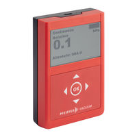
Pfeiffer Vacuum TPG 202 NEO Operating Instructions Manual (108 pages)
Piezo/Pirani handheld measurement instrument
Brand:
Pfeiffer Vacuum
| Category:
Measuring Instruments
| Size: 5 MB
Table of Contents
Dear Customer
2
Disclaimer of Liability
2
Telegramm Beispiel
2
Telegram Example
2
Table of Contents
3
Zu dieser Anleitung
7
Gültigkeit
7
Mitgeltende Dokumente
7
Varianten
7
Zielgruppe
7
Konventionen
7
Anweisungen IM Text
7
Piktogramme
8
Aufkleber auf dem Produkt
8
Abkürzungen
8
Markennachweis
8
Sicherheit
9
Allgemeine Sicherheitshinweise
9
Sicherheitshinweise
9
Sicherheitsmaßnahmen
11
Einsatzgrenzen des Produkts
11
Bestimmungsgemäße Verwendung
12
Vorhersehbarer Fehlgebrauch
12
Produktbeschreibung
13
Produkt Identifizieren
13
Funktion und Aufbau
13
Aufbau des Displays
13
Aufbau der Tastatur
14
Messprinzip
14
Anschluss USB
14
Lieferumfang
14
Transport und Lagerung
16
Produkt Transportieren
16
Produkt Lagern
16
Installation
17
Vakuumanschluss Herstellen
17
USB-Kabel Anschließen
17
Schnittstellen
19
Schnittstelle USB
19
Pfeiffer Vacuum Protokoll für USB-Schnittstelle
19
Telegrammrahmen
19
Telegrammbeschreibung
19
Telegramm Beispiel
20
Datentypen
20
Parametersatz
22
Allgemeines
22
Stellbefehle
22
Statusabfragen
22
Sollwertvorgaben und Druckwertabfrage
23
Betrieb
24
Akku Aufladen
24
Handmessgerät Einschalten
24
Handmessgerät Ausschalten
25
Gerät mit der Tastatur Bedienen
25
Tastatursperre Ein- und Ausschalten
25
Betriebsart Auswählen
25
Zusatzinformation Aufrufen
26
Hauptmenü Aufrufen und Verlassen
27
Daten mit dem Datenlogger Aufzeichnen
27
Druckverlauf Graphisch Darstellen
28
Leckrate Berechnen
28
Einstellungen
30
Datenlogger Einstellen
30
Graphische Darstellung Einstellen
31
Sensor Einstellen
32
Handmessgerät Abgleichen
33
Gasartkorrekturfaktor Einstellen
33
Umschaltart zwischen den Sensoren Einstellen
33
Geräteeinstellungen Vornehmen
34
Optisches und Akustisches Warnsignal Einstellen
34
Maximalbetriebszeit Einstellen
36
Datum und Uhrzeit Einstellen
36
Sprache und Anzeigeeinheiten Einstellen
37
Schnittstellen Einstellen
37
Dateisystem des Datenspeichers Formatieren
38
Gerät auf Werkseinstellungen Zurücksetzen
38
Geräteinformationen
39
Ausbau
40
Wartung
41
Komponenten Reinigen
41
Handmessgerät Abgleichen
42
1Nullpunkt Abgleichen
43
2Atmosphärendruck Abgleichen
43
3Nullpunkt der Relativdruckanzeige Abgleichen
44
Firmware Aktualisieren
44
Sensor Austauschen
44
Akku Austauschen
45
Gehäusedeckel Austauschen
45
Störungen
46
Versand
47
Recycling und Entsorgung
48
Allgemeine Entsorgungshinweise
48
Handmessgerät Entsorgen
48
Ersatzteile
49
Zubehör
50
Zubehörinformationen
50
Zubehör Bestellen
50
Technische Daten und Abmessungen
51
Allgemeines
51
Technische Daten
51
Abmessungen
52
EG Konformitätserklärung
53
Konformitätserklärung
54
List of Tables
57
List of Figures
58
About this Manual
59
Validity
59
Applicable Documents
59
Variants
59
Target Group
59
Conventions
59
Instructions in the Text
59
Pictographs
60
Labels on Product
60
Abbreviations
60
Trademark Proof
60
Tbl. 1: Abbreviations Used
60
Safety
61
General Safety Information
61
Safety Instructions
61
Safety Precautions
63
Limits of Use of Product
63
Tbl. 2: Permissible Ambient Conditions
63
Proper Use
64
Foreseeable Improper Use
64
Product Description
65
Identifying the Product
65
Function and Design
65
Display Layout
65
Fig. 1: Design of the Handheld Measurement Instrument
65
Keyboard Layout
66
Measuring Principle
66
USB Connector
66
Scope of Delivery
66
Fig. 2: Display Layout (Measured Value Display)
66
Fig. 3: Keyboard with Arrow Keys and "OK" Button
66
Transport and Storage
68
Transporting Product
68
Storing Product
68
Installation
69
Establishing Vacuum Connection
69
Connecting USB Cable
69
Interfaces
71
USB Interface
71
Pfeiffer Vacuum Protocol for USB Interface
71
Telegram Frame
71
Telegram Description
71
Tbl. 3: Characteristics of the USB Interface
71
Telegram Example
72
Data Types
72
Parameter Set
74
General
74
Control Commands
74
Status Requests
74
Set Value Settings and Pressure Value Query
75
Operation
76
Charging the Rechargeable Battery
76
Switching on Handheld Measurement Instrument
76
Fig. 4: Measured Value Display Menu with the Current Measured Pressure
76
Switching off Handheld Measurement Instrument
77
Operating Unit with Keyboard
77
Switching Keyboard Lock on and off
77
Selecting Operating Mode
77
Tbl. 8: Keyboard Functions
77
Fig. 5: Symbol for Keyboard Lock in the Top Line
77
Calling up Additional Information
78
Fig. 6: Auto-Off and Continuous Operating Modes
78
Fig. 7: Additional Information
78
Opening and Quitting Main Menu
79
Logging Data with Data Logger
79
Fig. 8: Main Menu
79
Fig. 9: Start/Stop Data Logger
79
Displaying Pressure Curve Graphically
80
Calculating Leakage Rate
80
Fig. 10: Pressure/Time Diagram
80
Fig. 11: Using Measurement of Pressure Rise to Calculate Leakage Rate
80
Fig. 12: Example of Displayed Values for Measurement of Pressure Rise
80
Settings
82
Setting Data Logger
82
Fig. 13: Opening Settings Menu
82
Fig. 14: Set the Logging Interval
82
Fig. 15: Set the Logging Period (Auto Stop)
82
Setting Graphical Display Mode
83
Fig. 16: Select the Data Source (Datasource)
83
Fig. 17: Set the Measured Value Display Mode (Graph Mode)
83
Adjusting Sensors
84
Fig. 18: Set the Time Window for a Rolling Display (Graph Window)
84
Fig. 19: Set the y Axis (Graph Axis)
84
Fig. 20: Select the Data Source (Graph Datasource)
84
Handheld Measurement Instrument Calibration
85
Setting Gas Type Correction Factor
85
Setting Transition Type between Sensors
85
Fig. 21: Setting Gas Type Correction Factor
85
Fig. 22: Setting Your Own Gas Type Correction Factor
85
Configuring Device Settings
86
Adjusting Visual and Acoustic Warning Signal
86
Fig. 23: Setting Transition Type
86
Fig. 24: Setting Transition Pressure or Pressure Range
86
Fig. 25: Select the Measurement Signal for the Alarm
86
Fig. 26: Adjust the Alarm Volume
87
Fig. 27: Select the Switching Mode for the Alarm
87
Fig. 28: Set the Switching Values for the Alarm
87
Setting Maximum Operating Time
88
Setting Date and Time
88
Fig. 29: Setting Maximum Operating Time
88
Fig. 30: Setting Date and Time
88
Setting Language and Display Units
89
Adjusting Interfaces
89
Fig. 31: Setting Language and Display Units
89
Formatting Data Storage Device File System
90
Resetting Unit to the Factory Settings
90
Fig. 32: Adjusting USB Interface
90
Device Information
91
Fig. 33: Calling up Unit Information
91
Fig. 34: Calling up Sensor Information
91
Dismantling
92
Maintenance
93
Cleaning Components
93
Handheld Measurement Instrument Calibration
94
Fig. 35: Selecting Calibration
94
1Zero Point Calibration
95
2Calibrating Atmospheric Pressure
95
Fig. 36: Zero Point Calibration
95
Fig. 37: Calibrating Atmospheric Pressure
95
3Calibrating Zero Point of Relative Pressure Display
96
Updating Firmware
96
Replacing Sensor
96
Fig. 38: Calibrating Zero Point of Relative Pressure Display
96
Replacing Rechargeable Battery
97
Replacing Housing Cover
97
Malfunctions
98
Shipping
99
Recycling and Disposal
100
General Disposal Information
100
Disposing of Handheld Measurement Instrument
100
Spare Parts
102
Tbl. 10: Spare Parts
102
Accessories
103
Accessory Information
103
Ordering Accessories
103
Technical Data and Dimensions
104
General
104
Technical Data
104
Tbl. 11: Conversion Table: Pressure Units
104
Tbl. 12: Conversion Table: Units for Gas Throughput
104
Dimensions
105
Tbl. 13: Technical Data
105
Fig. 39: Dimensions
105
EC Declaration of Conformity
106
Declaration of Conformity
107
Advertisement
Pfeiffer Vacuum TPG 202 NEO Operating Instructions Manual (56 pages)
Piezo/Pirani handheld measurement instrument
Brand:
Pfeiffer Vacuum
| Category:
Measuring Instruments
| Size: 4 MB
Table of Contents
Dear Customer
2
Disclaimer of Liability
2
Telegram Example
2
Table of Contents
3
List of Tables
5
List of Figures
6
About this Manual
7
Validity
7
Applicable Documents
7
Variants
7
Target Group
7
Conventions
7
Instructions in the Text
7
Pictographs
8
Labels on Product
8
Abbreviations
8
Trademark Proof
8
Tbl. 1: Abbreviations Used
8
Safety
9
General Safety Information
9
Safety Instructions
9
Safety Precautions
11
Limits of Use of Product
11
Tbl. 2: Permissible Ambient Conditions
11
Proper Use
12
Foreseeable Improper Use
12
Product Description
13
Identifying the Product
13
Function and Design
13
Display Layout
13
Fig. 1: Design of the Handheld Measurement Instrument
13
Keyboard Layout
14
Measuring Principle
14
USB Connector
14
Scope of Delivery
14
Fig. 2: Display Layout (Measured Value Display)
14
Fig. 3: Keyboard with Arrow Keys and "OK" Button
14
Transport and Storage
16
Transporting Product
16
Storing Product
16
Installation
17
Establishing Vacuum Connection
17
Connecting USB Cable
17
Interfaces
19
USB Interface
19
Pfeiffer Vacuum Protocol for USB Interface
19
Telegram Frame
19
Telegram Description
19
Tbl. 3: Characteristics of the USB Interface
19
Telegram Example
20
Data Types
20
Parameter Set
22
General
22
Control Commands
22
Status Requests
22
Tbl. 4: Explanation and Meaning of the Parameters
22
Tbl. 5: Parameter Set | Control Commands
22
Tbl. 6: Parameter Set | Status Requests
22
Set Value Settings and Pressure Value Query
23
Tbl. 7: Parameter Set | Set Value Settings and Pressure Value Query
23
Operation
24
Charging the Rechargeable Battery
24
Switching on Handheld Measurement Instrument
24
Fig. 4: Measured Value Display Menu with the Current Measured Pressure
24
Switching off Handheld Measurement Instrument
25
Operating Unit with Keyboard
25
Switching Keyboard Lock on and off
25
Selecting Operating Mode
25
Tbl. 8: Keyboard Functions
25
Fig. 5: Symbol for Keyboard Lock in the Top Line
25
Calling up Additional Information
26
Fig. 6: Auto-Off and Continuous Operating Modes
26
Fig. 7: Additional Information
26
Opening and Quitting Main Menu
27
Logging Data with Data Logger
27
Fig. 8: Main Menu
27
Fig. 9: Start/Stop Data Logger
27
Displaying Pressure Curve Graphically
28
Calculating Leakage Rate
28
Fig. 10: Pressure/Time Diagram
28
Fig. 11: Using Measurement of Pressure Rise to Calculate Leakage Rate
28
Fig. 12: Example of Displayed Values for Measurement of Pressure Rise
28
Settings
30
Setting Data Logger
30
Fig. 13: Opening Settings Menu
30
Fig. 14: Set the Logging Interval
30
Fig. 15: Set the Logging Period (Auto Stop)
30
Setting Graphical Display Mode
31
Fig. 16: Select the Data Source (Datasource)
31
Fig. 17: Set the Measured Value Display Mode (Graph Mode)
31
Adjusting Sensors
32
Fig. 18: Set the Time Window for a Rolling Display (Graph Window)
32
Fig. 19: Set the y Axis (Graph Axis)
32
Fig. 20: Select the Data Source (Graph Datasource)
32
Handheld Measurement Instrument Calibration
33
Setting Gas Type Correction Factor
33
Setting Transition Type between Sensors
33
Fig. 21: Setting Gas Type Correction Factor
33
Fig. 22: Setting Your Own Gas Type Correction Factor
33
Configuring Device Settings
34
Adjusting Visual and Acoustic Warning Signal
34
Fig. 23: Setting Transition Type
34
Fig. 24: Setting Transition Pressure or Pressure Range
34
Fig. 25: Select the Measurement Signal for the Alarm
34
Fig. 26: Adjust the Alarm Volume
35
Fig. 27: Select the Switching Mode for the Alarm
35
Fig. 28: Set the Switching Values for the Alarm
35
Setting Maximum Operating Time
36
Setting Date and Time
36
Fig. 29: Setting Maximum Operating Time
36
Fig. 30: Setting Date and Time
36
Setting Language and Display Units
37
Adjusting Interfaces
37
Fig. 31: Setting Language and Display Units
37
Formatting Data Storage Device File System
38
Resetting Unit to the Factory Settings
38
Fig. 32: Adjusting USB Interface
38
Device Information
39
Fig. 33: Calling up Unit Information
39
Fig. 34: Calling up Sensor Information
39
Dismantling
40
Maintenance
41
Cleaning Components
41
Handheld Measurement Instrument Calibration
42
Fig. 35: Selecting Calibration
42
1Zero Point Calibration
43
2Calibrating Atmospheric Pressure
43
Fig. 36: Zero Point Calibration
43
Fig. 37: Calibrating Atmospheric Pressure
43
3Calibrating Zero Point of Relative Pressure Display
44
Updating Firmware
44
Replacing Sensor
44
Fig. 38: Calibrating Zero Point of Relative Pressure Display
44
Replacing Rechargeable Battery
45
Replacing Housing Cover
45
Malfunctions
46
Tbl. 9: Malfunctions
46
Shipping
47
Recycling and Disposal
48
General Disposal Information
48
Disposing of Handheld Measurement Instrument
48
Spare Parts
50
Tbl. 10: Spare Parts
50
Accessories
51
Accessory Information
51
Ordering Accessories
51
Technical Data and Dimensions
52
General
52
Technical Data
52
Tbl. 11: Conversion Table: Pressure Units
52
Tbl. 12: Conversion Table: Units for Gas Throughput
52
Dimensions
53
Tbl. 13: Technical Data
53
Fig. 39: Dimensions
53
EC Declaration of Conformity
54
Declaration of Conformity
55
Advertisement
Related Products
Pfeiffer Vacuum TPG 202
Pfeiffer Vacuum TPG 201
Pfeiffer Vacuum TPG 361
Pfeiffer Vacuum TPG 362
Pfeiffer Vacuum TPR 280
Pfeiffer Vacuum TPR 281
Pfeiffer Vacuum TPR 265
Pfeiffer Vacuum TTR 91
Pfeiffer Vacuum TTR 91 S
Pfeiffer Vacuum TTR 96 S
Pfeiffer Vacuum Categories
Water Pump
Control Unit
Measuring Instruments
Industrial Equipment
Security Sensors
More Pfeiffer Vacuum Manuals
Login
Sign In
OR
Sign in with Facebook
Sign in with Google
Upload manual
Upload from disk
Upload from URL