Sign In
Upload
Manuals
Brands
Pfeiffer Vacuum Manuals
Water Pump
HIPACE 300 PLUS
Pfeiffer Vacuum HIPACE 300 PLUS Manuals
Manuals and User Guides for Pfeiffer Vacuum HIPACE 300 PLUS. We have
1
Pfeiffer Vacuum HIPACE 300 PLUS manual available for free PDF download: Operating Instructions Manual
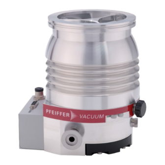
Pfeiffer Vacuum HIPACE 300 PLUS Operating Instructions Manual (120 pages)
Turbopump
Brand:
Pfeiffer Vacuum
| Category:
Water Pump
| Size: 9 MB
Table of Contents
Deutsch
3
Table of Contents
3
Gültigkeit
7
Mitgeltende Dokumente
7
Varianten
7
Zielgruppe
7
Konventionen
7
Anweisungen IM Text
7
Zu dieser Anleitung
7
Piktogramme
8
Aufkleber auf dem Produkt
8
Abb. 1: Position der Aufkleber auf dem Produkt
8
Abkürzungen
9
Markennachweis
9
Sicherheitshinweise
10
Sicherheit
10
Allgemeine Sicherheitshinweise
10
Sicherheitsmaßnahmen
14
Einsatzgrenzen des Produkts
15
Bestimmungsgemäße Verwendung
15
Vorhersehbarer Fehlgebrauch
16
Personenqualifikation
16
Personenqualifikation Sicherstellen
16
Personenqualifikation bei Wartung und Reparatur
17
Mit Pfeiffer Vacuum Weiterbilden
17
Rotorlager
18
Antrieb
18
Abb. 2: Aufbau Hipace 300 Plus
18
Kühlung
18
Funktion
18
Produktbeschreibung
18
Produkt Identifizieren
19
Produkttypen
19
Produktmerkmale
19
Lieferumfang
19
Transport und Lagerung
20
Lagerung
20
Transport
20
Installation
21
Vorbereitende Arbeiten
21
Turbopumpe am Unterteil Befestigen
22
Hochvakuumseite Anschließen
22
Anforderungen für die Auslegung des Gegenflansches
22
Erdbebensicherheit Berücksichtigen
23
Abb. 3: Beispiel: Sicherheitsverbindungen
24
Splitterschutz oder Schutzgitter Verwenden
24
Dämpfungskörper Verwenden
24
Einbaulagen
25
ISO-K Flansch an ISO-K Befestigen
25
Abb. 4: Vorgeschriebene Ausrichtung
25
Abb. 5: Flanschverbindung ISO-K zu ISO-K, Klammerschraube
25
ISO-K Flansch an ISO-F Befestigen
26
Abb. 6: Flanschverbindung ISO-K mit ISO-F, Sechskantschraube und Gewindeboh
26
Abb. 7: Flanschverbindung ISO-K mit ISO-F, Stiftschraube und Gewindebohrung
26
ISO-F Flansch an ISO-F Befestigen
27
Abb. 8: Flanschverbindung ISO-K mit ISO-F, Stiftschraube und Durchgangsbohrung
27
Abb. 9: Flanschverbindung ISO-F, Sechskantschraube und Gewindebohrung
27
CF-Flansch an CF-F Befestigen
28
Abb. 10: Flanschverbindung ISO-F, Stiftschraube und Gewindebohrung
28
Abb. 11: Flanschverbindung ISO-F, Stiftschraube und Durchgangsbohrung
28
Abb. 14: Flanschverbindung CF-F, Siftschraube und Durchgangsbohrung
29
Abb. 13: Flanschverbindung CF-F, Siftschraube und Gewindebohrung
29
Abb. 12: Flanschverbindung CF-F, Sechskantschraube und Durchgangsbohrung
29
Vorvakuumseite Anschließen
30
Abb. 15: Beispiel für den Vorvakuumanschluss an Hipace
30
Zubehör Anschließen
31
Elektrische Versorgung Anschließen
31
Abb. 16: Beispiel für den Zubehöranschluss über Adapter TCS
31
Turbopumpe Erden
32
Elektrischen Anschluss Herstellen
32
Abb. 17: Beispiel: Anschluss des Erdungskabels
32
Abb. 18: Antriebselektronik mit Netzteil Verbinden
33
Betrieb
34
Inbetriebnahme
34
Betriebsarten
34
Betrieb über Anschluss "E74
35
Betrieb über Feldbus
35
Betrieb über Multifunktionsanschluss "X3
35
Betrieb über Pfeiffer Vacuum Steuergerät
35
Betrieb ohne Bedieneinheit
35
Turbopumpe Einschalten
36
Betriebsüberwachung
36
Betriebsanzeige über LED
36
Temperaturüberwachung
37
Ausschalten und Fluten
37
Ausschalten
37
Fluten
37
Wartung
39
Allgemeine Wartungshinweise
39
Checkliste für Inspektion und Wartung
39
Betriebsmittelspeicher Austauschen
40
Betriebsmittelspeicher Demontieren
41
Betriebsmittelspeicher Montieren
42
Antriebselektronik Austauschen
43
Antriebselektronik Demontieren
43
Antriebselektronik Installieren
44
Drehzahlvorgabe Bestätigen
45
Außerbetriebnahme
46
Stillsetzen für Längere Zeit
46
Wiederinbetriebnahme
46
Recycling und Entsorgung
47
Allgemeine Entsorgungshinweise
47
Turbopumpe Entsorgen
47
Störungen
48
Servicelösungen von Pfeiffer Vacuum
50
Ersatzteile
52
Zubehör Bestellen
53
Zubehörinformationen
53
Zubehör
53
Technische Daten und Abmessungen
55
Allgemeines
55
Technische Daten
55
Medienberührende Werkstoffe
57
Abmessungen
57
EG Konformitätserklärung
59
Konformitätserklärung
60
English
61
About this Manual
65
Applicable Documents
65
Conventions
65
Instructions in the Text
65
Target Group
65
Validity
65
Variants
65
Fig. 1: Position of the Stickers on the Product
66
Pictographs
66
Stickers on Product
66
Abbreviations
67
Tbl. 1: Abbreviations Used in this Document
67
Trademark Proof
67
General Safety Information
68
Safety
68
Safety Instructions
68
Safety Precautions
72
Foreseeable Improper Use
73
Limits of Use of Product
73
Proper Use
73
Tbl. 2: Permissible Ambient Conditions
73
Ensuring Personnel Qualification
74
Personnel Qualification
74
Advanced Training with Pfeiffer Vacuum
75
Personnel Qualification for Maintenance and Repair
75
Cooling
76
Drive
76
Fig. 2: Design Hipace 300 Plus
76
Function
76
Product Description
76
Rotor Bearing
76
Identifying the Product
77
Product Features
77
Product Types
77
Scope of Delivery
77
Storage
78
Transport
78
Transportation and Storage
78
Fastening Turbopump to Bottom Part
79
Installation
79
Preparatory Work
79
Connecting the High Vacuum Side
80
Requirements for the Dimensioning of a Counter Flange
80
Tbl. 5: Requirements for Fastening the Turbopumps to the Bottom Part
80
Considering Earthquake Protection
81
Fig. 3: Example: Safety Connections
81
Tbl. 6: Requirements for the Dimensioning of Customer-Specific High Vacuum con
81
Tbl. 7: Reduction of the Pumping Speed When Using a Splinter Shield or Protective
81
Using a Splinter Shield or Protective Screen
81
Fig. 4: Prescribed Alignment
82
Mounting Orientations
82
Using the Vibration Compensator
82
Attaching ISO-K Flange Onto ISO-K
83
Attaching ISO-K Flange to ISO-F
83
Fig. 5: Flange Connection ISO-K to ISO-F, Bracket Screws
83
Fig. 6: Flange Connection ISO-K with ISO-F, Hexagon Head Screw and Tapped Hole
83
Attaching ISO-F Flange to ISO-F
84
Fig. 7: Flange Connection ISO-K with ISO-F, Stud Screw and Tapped Hole
84
Fig. 8: Flange Connection ISO-K with ISO-F, Stud Screw and through Hole
84
Attaching CF Flange to CF-F
85
Fig. 10: Flange Connection ISO-F, Stud Screw and Tapped Hole
85
Fig. 11: Flange Connection ISO-F, Stud Screw and through Hole
85
Fig. 9: Flange Connection ISO-F, Hexagon Head Screw and Tapped Hole
85
Fig. 12: Flange Connection CF-F, Hexagon Head Screw and through Hole
86
Fig. 13: Flange Connection CF-F, Stud Screw and Tapped Hole
86
Connecting the Fore-Vacuum Side
87
Fig. 14: Flange Connection CF-F, Stud Screw and through Hole
87
Connecting Accessories
88
Fig. 15: Example of Fore-Vacuum Connection on Hipace
88
Connecting the Electrical Supply
89
Earthing the Turbopump
89
Fig. 16: Example of Accessory Connection Via Adapter TCS
89
Establishing Electric Connection
90
Fig. 17: Example: Connecting the Grounding Cable
90
Fig. 18: Connecting Electronic Drive Unit to Power Supply Pack
91
Commissioning
92
Operation
92
Tbl. 8: Factory Setting of the Electronic Drive Unit for Turbopumps When Delivered
92
Operating Modes
93
Operation Via Connection "E74
93
Operation Via Field Bus
93
Operation Via Multi-Function Connection "X3
93
Operation Via Pfeiffer Vacuum Control Unit
93
Operation Without Operating Unit
93
Operating Mode Display Via LED
94
Operation Monitoring
94
Switching on the Turbopump
94
Switching off
95
Switching off and Venting
95
Tbl. 9: Behavior and Meaning of the Leds on the Electronic Drive Unit
95
Temperature Monitoring
95
Venting
95
Tbl. 10: Factory Settings for Delayed Venting in Turbopumps
96
Checklist for Inspection and Maintenance
97
General Maintenance Information
97
Maintenance
97
Replace Operating Fluid Reservoir
98
Tbl. 11: Maintenance Intervals
98
Fig. 19: Removing the Operating Fluid Reservoir
99
Removing the Operating Fluid Reservoir
99
Fig. 20: Installing the Operating Fluid Reservoir
100
Installing the Operating Fluid Reservoir
100
Removing Electronic Drive Unit
101
Replacing Electronic Drive Unit
101
Fig. 21: Removal of Electronic Drive Unit TC
102
Fig. 22: Installation of Electronic Drive Unit TC
102
Installing Electronic Drive Unit
102
Confirming Speed Specification
103
Tbl. 12: Characteristic Nominal Rotation Speeds of the Turbopumps
103
Decommissioning
104
Recommissioning
104
Shutting down for Longer Periods
104
Dispose of Turbopumps
105
General Disposal Information
105
Recycling and Disposal
105
Malfunctions
106
Tbl. 13: Troubleshooting Turbopumps
107
Service Solutions by Pfeiffer Vacuum
108
Fig. 23: Spare Parts Hipace 300 Plus
110
Spare Parts
110
Accessories
111
Accessory Information
111
Ordering Accessories
111
Tbl. 15: Accessories
112
General
113
Technical Data
113
Technical Data and Dimensions
113
Dimensions
115
Fig. 24: Dimensions Hipace 300 | TC 110 | DN 100 ISO-K
115
Substances in Contact with the Media
115
Fig. 25: Dimensions Hipace 300 | TC 110 | DN 100 ISO-F
116
Fig. 26: Dimensions Hipace 300 | TC 110 | DN 100 CF-F
116
EC Declaration of Conformity
117
Declaration of Conformity
118
Advertisement
Advertisement
Related Products
Pfeiffer Vacuum HiCube 300 Eco
Pfeiffer Vacuum HiCube 300 Classic
Pfeiffer Vacuum HiPace 300 P
Pfeiffer Vacuum HiCube 300 Pro
Pfeiffer Vacuum HiCube 300 H Pro
Pfeiffer Vacuum HiCube 30 Eco
Pfeiffer Vacuum HIPACE 30 NEO
Pfeiffer Vacuum DUO 35 C
Pfeiffer Vacuum DUO 35 MC
Pfeiffer Vacuum HIPACE 350
Pfeiffer Vacuum Categories
Water Pump
Control Unit
Measuring Instruments
Industrial Equipment
Security Sensors
More Pfeiffer Vacuum Manuals
Login
Sign In
OR
Sign in with Facebook
Sign in with Google
Upload manual
Upload from disk
Upload from URL