Sign In
Upload
Manuals
Brands
Permalert Manuals
Control Panel
PAL-AT AT30C
Permalert PAL-AT AT30C Leak Detection Manuals
Manuals and User Guides for Permalert PAL-AT AT30C Leak Detection. We have
2
Permalert PAL-AT AT30C Leak Detection manuals available for free PDF download: Installation Manual, Operating Manual
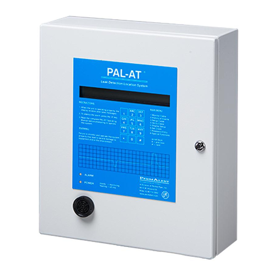
Permalert PAL-AT AT30C Operating Manual (62 pages)
Brand:
Permalert
| Category:
Measuring Instruments
| Size: 2.01 MB
Table of Contents
Table of Contents
3
Safety Information
6
1 Introduction
7
Theory of Operation
7
Start up
7
Installation Instructions
7
Initial Display
8
Time and Date Format
8
LCD Contrast Adjustment
8
Manual Updates
8
Wiring Diagrams
8
2 Operating PAL-AT
11
Setup
11
Multiple Cable System
11
Exit Setup
11
Baseline Check
11
Hydrocarbon Liquids with ZBA
12
Impedance Jumper Setting
12
Sensor String Sections
12
Create Setup Table
12
Select Cable Type
13
Probes
13
Enter Cable Distance
13
No End Found
14
AT-ORC Functions
14
End of Sensor String
14
Set Sensitivity
14
Reference Maps
15
Reference Process
15
Reference Map Rules
15
Reference Issues
16
Verify
16
Multiple Cable System
16
Select the Master Map
17
Verify Process
17
Select to Monitor
18
Monitor
18
Normal Messages Displayed
18
Fault Messages Displayed
19
Alarm Silence Feature
20
Alarm Queue
20
Failure to Enter Monitor Mode
20
Display Setup
21
Multiple Cable System
21
Display Setup Data
22
Last Section
22
Add Sections
22
Record the Setup Table
23
History of Events
23
History Messages - the First Line
23
History Messages - the Second Line
26
Set Clock
26
Set the Time and Date
26
Passwords
27
Establish New Passwords
27
Delete Password
28
Enter Password
28
Special Functions
28
Set Relay Normal States
28
Select Language
29
Set Special Options
29
Set Alarm Silence Time
29
Set Averaging Rate
29
Set Noise Factor
30
Set Autosilence
30
Set Baud Rates and Data Format
30
Set System Identification and Ethernet Addresses
31
Enter Phone Number
32
Display Cable Data
32
Multiple Cable System
32
Starting Distance
33
Set Test Mode
33
Communications Options
33
PALCOM 10 Software
34
Customer Software
34
Modbus RTU, TCP, and RTU over TCP
35
Function Code 3 - Read Registers
35
Function Code 16 - Preset Multiple Registers
35
Ethernet Auto-Negotiate Selection
37
3 Response to Alarms
37
Decisions
37
Locations
37
Types of Alarm Conditions
38
Fault
38
Break Alarm
38
Short Alarm
38
Drying or Probe Reset Alarm
38
Leak or Probe Activated Alarm
38
Leak Analysis
39
Accessible Applications - Raised Floor Systems
39
Inaccessible Applications - Contained Piping Systems
39
Direct Buried Applications
39
Repetitive Cycling Alarms
40
4 Tests and Maintenance
41
Select Test Mode
41
Alarm Test
41
Cable Test
41
Probe Test
41
Battery
41
Auxiliary Header
42
USB Port
43
Firmware Upgrade
43
Data Logger
43
5 Troubleshooting
45
Initial Power-Up Checks
45
System Board
45
Diagnostic Leds
45
Port 1 and 2 RS-232/485
45
Relays
45
DC Voltages
46
Cable Status
46
VDC Reversed Polarity
46
Zener Barrier Panel
47
Zener Barrier Assembly Tests
47
ZBA External Fuse
48
Cable Connector Tests
48
Troubleshooting Guide
49
Restrictions & Limitations
50
Sensor Cables
50
Probes
51
PAL-AT Setup Record
52
Appendix A - Output Relay System
54
Installation of Output Relay System
54
Relay Module Configuration
56
Internal Diagnostic Indicators
57
Control Relays
57
RS-232 Port Interface Cable Installation
58
PAL-AT Control of Output Relay System
58
Sensing Cable and Probe Requirements
58
Assign Output Relays
58
Display Output Relay Assignments
58
Change Output Relay Assignments
59
Warranty
60
Advertisement
Permalert PAL-AT AT30C Installation Manual (84 pages)
Brand:
Permalert
| Category:
Control Panel
| Size: 4.19 MB
Table of Contents
Table of Contents
3
Safety Information
7
1 Introduction
8
General Description
8
Applications
8
Receiving and Handling Precautions
8
Materials and Equipment Normally Supplied by Permalert
8
Materials and Equipment Normally Supplied by Installing Contractor
9
2 PAL-AT Alarm/Locator Panel
10
Alarm/Locator Panel Installation
10
Terminals
11
Power Connection
11
Audible Alarm Wiring
11
Control Relays
11
Communications
14
Port 1 - RS-485/RS-232
14
Port 2 - RS-232
14
Ethernet
14
Ethernet Auto-Negotiate Selection
15
Replaceable Parts
15
Battery
15
VDC Fuse
15
Contrast Adjustment
15
Impedance Jumper Setting
16
FCC and CE Compliance Requirements
16
3 Zener Barrier Panel
17
Introduction
17
Panel Installation
17
Panel Wiring
19
Zener Barrier Assembly (ZBA) Installation
19
Fuse Protection
19
Allowable Cables and Probes
19
4 Jumper Cable and Junction Box Installation
20
Jumper Cable
20
Calibration Points
21
Junction Boxes
21
5 Cable Installation in Secondary Contained Piping
22
General
22
Pull Points
23
Cable Splices
25
Factory Installed Fiber Pull Rope to Continuous Pull Wire Rope Splice
25
Wire Rope to Wire Rope Splice
26
Wire Rope to Wire Rope Splice (Alternate)
27
Wire Rope to Leak Detection Cables
28
Installation of the Continuous Pull Rope
30
Installing Sensor and Jumper Cables
32
Air Testing
35
6 Installation of Direct Buried Sensor Cable
36
General
36
Installing the Sensor Cable
37
Above Ground Storage Tanks
40
7 Cable Installation for Raised Floor and Ceilings
42
General
42
Install the Sensor Cable
42
Locator Chart
43
Calibration and End of Run Access Points
43
8 Cable Connectors
44
General
44
Cable Connector Installation
44
CAGOLD and CATFH Connectors for Sensor Cables AGW-Gold, AGT-Gold, TFH-Gold and TFH
44
CAJMP Connectors for Jumper Cables JMP-U/-UD
47
CAJPP Connectors for Jumper Cables JPP and JMP
49
CAGOLD Connector for ATP Cable
50
Shrink Tubing
52
Cable Type TFH
52
Cable Types AGW-Gold, AGT-Gold and TFH-Gold
53
Cable Types JMP-U/-UD, JPP and JMP
54
Cable and Connector Testing Procedures
54
General
54
Continuity Test
54
Alternative System Test
55
Insulation Test
55
Cable Connections to Panels
55
General
55
Ferrule Installation in PAL-AT Panel
55
Ferrule Installation in Zener Barrier Panel
57
ATP Cable Connection at PAL-AT
59
9 Probes
60
UL Requirements
60
Probe Integrator Selection
60
Probe Installation
60
PHLR Hydrocarbon Probe
62
Cleaning Sensor Elements Procedure
63
Testing the Probe
64
Troubleshooting
64
Calibrating the Probe
64
Typical Installations
65
Probe Tests
70
10 ATP Cable in Polyurethane Foam Insulation
72
General
72
Pipe Installation Precautions
72
System Configuration
72
Calibration Points
72
ATP Cable and Connector Testing Procedures
72
Continuity Test
73
Insulation Test
73
Insulation Test with Wet Cloth
74
Start of Run
74
ATP Cable Splices
75
ATP Cable at Tee Connections
77
End of Run Termination
78
Requirements for Field Joints with Wind-Down End Seals
79
Appendix A - Special Instructions
80
Supply Power
80
Control Drawing
80
Zener Barrier Panel (ZBP)
80
Probe Integrator
80
Probe Integrator Static Precautions
80
Advertisement
Related Products
Permalert PAL-AT AT75C
Permalert PAL-AT AT30K
Permalert PAL-AT AT20C
Permalert PAL-AT AT50C
Permalert PAL-AT AT20K
Permalert PAL-AT AT40K
Permalert PAL-AT AT80K
Permalert PAL-AT Series
Permalert PAL-AT20C
Permalert PAL-AT20K
Permalert Categories
Measuring Instruments
Security Sensors
Control Panel
More Permalert Manuals
Login
Sign In
OR
Sign in with Facebook
Sign in with Google
Upload manual
Upload from disk
Upload from URL