Table of Contents
Advertisement
Quick Links
Advertisement
Table of Contents

Related Manuals for Permalert PAL-AT AT30C

Summary of Contents for Permalert PAL-AT AT30C
- Page 2 NO LIABILITY FOR ANY DAMAGES INCURRED DIRECTLY OR INDIRECTLY FROM ANY TECHNICAL OR TYPOGRAPHICAL ERRORS OR OMISSIONS CONTAINED HEREIN OR FOR DISCREPANCIES BETWEEN THE PRODUCT AND THE MANUAL. IN NO EVENT SHALL PERMALERT BE LIABLE FOR ANY INCIDENTAL, CONSEQUENTIAL, SPECIAL, OR EXEMPLARY DAMAGES, WHETHER BASED ON TORT, CONTACT OR OTHERWISE, ARISING OUT OF OR IN CONNECTION WITH THIS MANUAL OR ANY OTHER INFORMATION CONTAINED HEREIN OR THE USE THEREOF.
-
Page 3: Table Of Contents
1.1 General Description ......................8 1.2 Applications ........................8 1.3 Receiving and Handling Precautions ................8 1.4 Materials and Equipment Normally Supplied by PermAlert ..........8 1.5 Materials and Equipment Normally Supplied by Installing Contractor ......9 PAL-AT Alarm/Locator Panel ..............10 2.1 Alarm/Locator Panel Installation .................. - Page 4 PAL-AT Installation Manual 4.2 Calibration Points ......................21 4.3 Junction Boxes ....................... 21 Cable Installation in Secondary Contained Piping ....... 22 5.1 General .......................... 22 5.2 Pull Points ........................23 5.3 Cable Splices ......................... 25 5.3.1 Factory Installed Fiber Pull Rope to Continuous Pull Wire Rope Splice ....25 5.3.2 Wire Rope to Wire Rope Splice ................
- Page 5 PAL-AT Installation Manual 8.4.3 Alternative System Test ..................55 8.4.4 Insulation Test ..................... 55 8.5 Cable Connections to Panels ..................55 8.5.1 General ........................ 55 8.5.2 Ferrule Installation in PAL-AT Panel ..............55 8.5.3 Ferrule Installation in Zener Barrier Panel ............57 8.5.4 ATP Cable Connection at PAL-AT ...............
- Page 6 PAL-AT Installation Manual A.6 ZBP Enclosure Fittings ....................81 WARRANTY ....................83...
-
Page 7: Safety Information
PAL-AT Installation Manual Safety Information Please Read This Installation Manual Please take the time to read this installation manual carefully. It will help you set up and operate your system properly. Failure to follow these instructions may impair the safety of the equipment. Please save this installation manual for future reference. -
Page 8: Introduction
PermAlert's products for their application and specific installation. If you receive a PermAlert product not described in this manual, contact PermAlert for the appropriate instructions. PermAlert is a division of Perma-Pipe, Inc. Refer to the PermAlert website, permalert.com, for the latest revision of manuals and product data sheets. -
Page 9: Materials And Equipment Normally Supplied By Installing Contractor
PAL-AT Installation Manual Maximum No. of Cable Connectors Enclosure Dimensions in Enclosure 6" x 6" x 4" [150 mm x 150 mm x 100 mm] 8" x 6" x 4" [200 mm x 150 mm x 100 mm] 10" x 8" x 4" [250 mm x 200 mm x 100 mm] 8. -
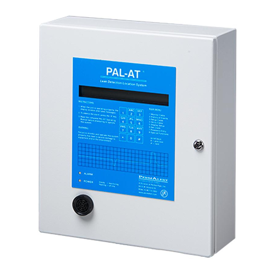
Page 10: Pal-At Alarm/Locator Panel
PAL-AT Installation Manual PAL-AT Alarm/Locator Panel Alarm/Locator Panel Installation The PAL-AT panel is designed to be permanently mounted indoors in a dry area. The enclosure is rated Type 12 [IP52]. It must not be located in direct sunlight to prevent excessive heat buildup. In all installations, the ambient temperature surrounding the PAL-AT panel must be within the limits below. -
Page 11: Terminals
PAL-AT Installation Manual Terminals The terminals on the PAL-AT system board use a quick-connect design that provides an easy, fast and robust connection. A flat blade screwdriver, 1/8” [3.5 mm], is used to press down on the terminal lever and open the terminal for easy wire insertion. Release the lever, and the wire is tightly clamped. The acceptable wire size for connection to any terminal, including the mains, is 28 - 12 AWG [0.08-2.5 ]. - Page 12 PAL-AT Installation Manual relays configured to operate in a normally de-energized mode, so they energize when the panel is in the alarm state (see the PAL-AT Operating Manual for changing relay configuration). Figure 2-2 Wiring Diagram for PAL-AT Models AT30C & AT75C...
- Page 13 PAL-AT Installation Manual Figure 2-3 Wiring Diagram for PAL-AT Model AT30K...
-
Page 14: Communications
PAL-AT Installation Manual Communications PAL-AT is provided with several options for communication. The options include: Port 1 – RS-485/RS-232 Port 2 – RS-232 Ethernet - RJ-45 connector Refer to the PAL-AT Operating Manual for complete operating details and firmware configuration. 2.6.1 Port 1 - RS-485/RS-232 Port 1 can be configured for RS-485 or RS-232 (refer to figures 2-2 and 2-3). -
Page 15: Ethernet Auto-Negotiate Selection
Fire. It can be obtained locally or through PermAlert. It is replaceable by gently lifting the retaining clip to remove the old battery and sliding in the new one. Be careful to install the battery correctly. The lettering on the battery (+) should be facing out. -
Page 16: Impedance Jumper Setting
250 VAC. 2.11 FCC and CE Compliance Requirements Each PAL-AT system is supplied with several "ferrite blocks" (PermAlert part # 8058207) to comply with FCC and CE regulations for a Class A digital device. The sensor cables, jumper cables, and all communications wires must pass through two blocks before exiting the enclosure (see figure 2-4). -
Page 17: Zener Barrier Panel
Zener Barrier Panel Introduction The optional Zener Barrier Panel (ZBP) is available for connection to PAL-AT when leak detection cables and probes are installed in hazardous locations. It provides intrinsically safe output circuits for use in Class I, Division 1 Groups C and D hazardous locations (Zone 0, Group IIB) when used with PAL-AT sensor cables, jumper cables, and probes, installed in accordance with the instructions in this manual. - Page 18 DC POWER SWITCH SURGE SUPPRESSOR REPLACEMENT FUSE CABLE TO ZBP FOR HAZARDOUS LOCATIONS CABLE OUTPUT TO HAZARDOUS LOCATION CABLE CONNECTOR PAL-AT AT30C/AT75C/AT30K OPTIONAL ZBP CABLE TO ORDINARY Figure LOCATIONS PAL-AT and Zener Barrier Panel Figure 3-3 Zener Barrier Panel (ZBP) Wiring...
-
Page 19: Panel Wiring
Each Zener Barrier Assembly is protected from external voltage surges by a replaceable fuse in the terminal strip fuse holder. The 5 x 20 mm fuse is rated 250 mA, 250 V, fast-acting (Littelfuse 0217.250 or equal). A replacement may be purchased from PermAlert (part # 8067989) or obtained locally. Allowable Cables and Probes Refer to Appendix A –... -
Page 20: Jumper Cable And Junction Box Installation
5. Where possible, jumper cable connections to sensor cable should be made within the monitored area. PermAlert recommends the use of OZ Gedney, or equal, cord grips installed as shown in figure 4-1. Cord grips must clamp only jumper cable or TFH cable. The plastic outer braid on TFH cable must be pulled back so the cord grip is located on the smooth outer jacket. -
Page 21: Calibration Points
500' [150 m] will have a location accuracy of less than +/- 1% of the cable length from the previous calibration point. Junction Boxes There are two series of junction boxes supplied by PermAlert. The standard, polyester box has a maximum temperature rating of 150°F [65°C]. A fiberglass box is available for temperatures to 300°F [150°C]. -
Page 22: Cable Installation In Secondary Contained Piping
Because the sensor cable is placed on the bottom of the air space, there must be a continuous unobstructed passage for the cable(s) being pulled into the system. PermAlert recommends a 1" [25 mm] air space. Pipe support design and alignment is critical. Pipe supports and other surfaces the cable contacts during “pulling”... -
Page 23: Pull Points
Note: 1. Not all pipe types or sizes are shown in the above charts. For different systems, contact PermAlert. 2. Chart is based on smooth pulling surfaces and installation of guide tubes. 3. Multi pipe system will require factory sizing. - Page 24 PAL-AT Installation Manual 4. Pull ports may also be used for periodic testing. If so, a short length of sensor cable (minimum 5’ - AGW-Gold, 15’ – TFH/TFH-Gold) with connectors should be installed in the pull port during the initial setup.
-
Page 25: Cable Splices
PAL-AT Installation Manual Cable Splices Continuous pull rope and sensor cable are "pulled" into the secondary containment during certain stages of installation. Several splices are used to provide secure attachments to pull ropes and cable during this procedure. The following methods are recommended for splicing. Note: When using tape to seal the splices, use only PVC electrical tape. -
Page 26: Wire Rope To Wire Rope Splice
PAL-AT Installation Manual 5.3.2 Wire Rope to Wire Rope Splice Step A Extend 12" to 18" [300 mm to 450 mm] of each wire rope end for the splice. Step B Unravel each of the 12" to 18" ends into a 3-strand and a 4-strand section (approximately 50% in each), keeping the adjacent strands together. -
Page 27: Wire Rope To Wire Rope Splice (Alternate)
PAL-AT Installation Manual 5.3.3 Wire Rope to Wire Rope Splice (alternate) Note: Use this splice when splicing two different size wire ropes together Step A Extend 8"-10" [200 mm to 250 mm] of each wire rope to be spliced. Step B Unravel each of the 8"-10" sections (to approximately the same length) into two sections to form a Y with three adjacent spiral strands on one side, three adjacent spiral strands with center strand on the other. -
Page 28: Wire Rope To Leak Detection Cables
PAL-AT Installation Manual 5.3.4 Wire Rope to Leak Detection Cables The following steps apply in general to all sensor and jumper cables. However, there may be slight variations to the steps presented depending on the cable selected. For example, the jumper cables have an outer jacket but no plastic overbraid, while the TFH cable has both a jacket and an overbraid. - Page 29 PAL-AT Installation Manual Step F Cut 5" [125 mm] off the exposed end of the sensing cable. Step G Cut off 15"-18" [380 mm to 450 mm] of the outer jacket and tightly tape the edge of the outer jacket to the metallic braid.
-
Page 30: Installation Of The Continuous Pull Rope
The finished splice should be tapered in appearance. Installation of the Continuous Pull Rope 1. PermAlert recommends the installation of a continuous pull rope, free of splices between properly located and accessible pull points. 2. All sections of factory-prefabricated piping should be supplied with a factory-installed pull rope. The factory-installed ropes shall be used to pull the continuous pull rope into the air space before the secondary containment field joint closures are completed. - Page 31 PAL-AT Installation Manual 5. Caution all workers involved in the pipe installation that the factory installed pull rope should never be “temporarily” removed with the expectation it can be replaced later. Losing the end of the pull rope and allowing it to fall back inside the secondary containment must be avoided. Special care must be taken at risers where the weight of the rope, in the vertical section of the pipe, tends to pull the rope into the secondary containment.
-
Page 32: Installing Sensor And Jumper Cables
Care must be taken during installation of sensor cable to avoid contact with potential contaminants such as water puddles or oil. 2. PermAlert recommends installing the sensor cable before backfilling of underground secondary contained pipe systems. - Page 33 11. The pulling force should never exceed 50 lb [23 kg]. If a snag is encountered, carefully work the cable back and forth in an attempt to clear the cable. If the snag cannot be cleared, contact PermAlert's Field Service Department for assistance.
- Page 34 PAL-AT Installation Manual drawing showing locations requiring the installation of sensor cable and jumper. Depending on the design of the secondary contained system and the free unobstructed air space available, both cables (sensor and jumper) may be installed in the secondary containment air space. This will require simultaneously pulling both cables, and most likely will reduce the length of cables that can be pulled at one time.
-
Page 35: Air Testing
PAL-AT Installation Manual Air Testing 1. Air testing of the secondary containment must be performed before backfilling. 2. All sensor cable termination chambers (see figures 5-3 and 5-4) must be completely installed before applying the air test. Also, cap any open vents or drains. Be careful to prevent the pull rope or sensor cable from being blown back into the secondary containment. -
Page 36: Installation Of Direct Buried Sensor Cable
If you have any questions regarding the installation of the direct buried cables, contact PermAlert. Failure to follow these instructions may result in damage to the cables or its jacket and prevent or limit operation of the PAL-AT system. -
Page 37: Installing The Sensor Cable
PAL-AT Installation Manual 8. If a synthetic liner is not installed under the slotted pipe, a compacted clay/silt base layer should be used under the pipe to minimize the vertical migration of a leak. The slotted pipe should be covered with backfill material of sand or soil. - Page 38 PAL-AT Installation Manual Figure 6-1 Direct Buried TFH/TFH-Gold Hydrocarbon Sensor Cables...
- Page 39 PAL-AT Installation Manual Figure 6-2 Hydrant Valve Pit / Manhole Penetration Direct Buried Cable...
-
Page 40: Above Ground Storage Tanks
Above ground storage tanks can be monitored for leaks by installing TFH/TFH-Gold sensor cable in slotted PVC pipe under the bottom of the tank or around the perimeter. Figures 6-3 and 6-4 show two such applications. For specific applications, contact PermAlert for assistance. Figure 6-3... - Page 41 PAL-AT Installation Manual Figure 6-4 Above Ground Storage Tank Horizontal Drilling...
-
Page 42: Cable Installation For Raised Floor And Ceilings
It also absorbs moisture from the air if the air is saturated or near saturation. PermAlert recommends a maximum of 80% relative humidity, keeping in mind the relative humidity will increase if the temperature of the air or a surface in the airflow decreases. In subfloor applications, care must be taken to make sure the cable is not located directly in the airflow where localized higher humidity or saturated air is present. -
Page 43: Locator Chart
PAL-AT Installation Manual 9. Cable mounts (CMA) ordered from PermAlert are adhesive backed. When installations require mounting to unsealed concrete surfaces, it is recommended construction mastic be used. Care must be taken to ensure the mastic does not touch the sensor cable. This material can be purchased from most supply houses. -
Page 44: Cable Connectors
(3) the electrical testing of connectors and cable. All connectors are crimp style and soldering is not required. Instructional videos for Cable Connector Installations are available at the PermAlert web site, www.permalert.com. WARNING For Hazardous Locations – Some cable connectors are located in NEMA 4X [IP66] junction boxes that are made of plastic and as such, present a possible electrostatic hazard. - Page 45 PAL-AT Installation Manual For AGT-Gold, slide the braid wire back 2” [50 mm] and remove 1 7/8” [47 mm] of the yarn spacer. Then insert the sanding tool 3” [75 mm] over the center conductor and slide the braid wire back over the tool.
- Page 46 UHF plug body. Caution: Once the crimp tool (PermAlert Part No. 8068301) starts to close, it must be closed completely before it will open again. Position the crimp tool (0.255" die) carefully around the outer ferrule and crimp Crimp the end of the center contact as shown using a 0.100"...
-
Page 47: Cajmp Connectors For Jumper Cables Jmp-U/-Ud
1/8” [3 mm] past the end of the connector. Caution: Once the crimp tool (PermAlert Part No. 8068300) starts to close, it must be closed completely before it can be opened again. Position the crimp tool 0.429" die carefully around the outer ferrule and crimp it. - Page 48 PAL-AT Installation Manual The procedure for crimping the center conductor requires a short length of #14 AWG solid copper wire to fill the center contact of the connector. Strip 3/8” of insulation from the wire. Bend the end of the strands of the center conductor slightly to the side. Next, carefully slide the bare #14 AWG wire all the way into the center contact as shown.
-
Page 49: Cajpp Connectors For Jumper Cables Jpp And Jmp
UHF plug body and the plastic core will be inside the center contact. Caution: Once the crimp tool (PermAlert Part No. 8068300) starts to close, it must be closed completely before it can be opened again. Crimp the center contact... -
Page 50: Cagold Connector For Atp Cable
PAL-AT Installation Manual Step E Slide the UHF coupling ring onto the plug. Slide the outer ferrule (and the remaining foil, if any, for JPP cable) over the braid and up to the UHF plug body. Make sure the braid extends slightly past the end of the outer ferrule against the UHF plug body. - Page 51 PAL-AT Installation Manual Step E Next, take the crimp tool and clamp the 0.255” die around the twisted wires behind the outer ferrule. Be careful not to pinch the wires. They should slide freely through the die. Then push the plug body toward the crimp tool to force the outer ferrule and white wire to slide over the inner ferrule until they are tight against the plug shoulder as shown in the second view.
-
Page 52: Shrink Tubing
PAL-AT Installation Manual Shrink Tubing All cable connectors installed in inaccessible locations or locations subject to frequent leaks or corrosive environments must be encapsulated with shrink tubing. This applies to sensor cables and jumper cables. Connectors used for calibration points should not be sealed until the system has been brought online unless they may be exposed to water before start-up. -
Page 53: Cable Types Agw-Gold, Agt-Gold And Tfh-Gold
PAL-AT Installation Manual Step D After both cable ends have been sealed with the 4” [100 mm] shrink tubing, recheck that the connectors are tightened securely. Test the connector according to the "Cable and Connector Testing Procedures". Then slide and center the 8" [200 mm] shrink tubing over the connector and heat it until it is fully shrunk and adhesive oozes out the ends. -
Page 54: Cable Types Jmp-U/-Ud, Jpp And Jmp
3. The ohmmeter reading should be less than 10 ohms/1000' [10 ohms/300 m] of cable. If it is not, check the jumper wire, test lead connections, and repeat the test. If the problem persists, contact the PermAlert Field Service Department for assistance. -
Page 55: Alternative System Test
2. A good cable will give a full-scale reading (at least 10 megohms). Test readings below full scale indicate damaged cable or an improperly installed connector. If you cannot resolve the problem, contact PermAlert's Field Service Department for assistance. Figure 8-1... - Page 56 PAL-AT Installation Manual touching the sticky, water-blocking material. Twist each group into a small wire. Remove 1.0” [25 mm] of insulation from the center wire. Step C JMP-U/-UD Cable Slide a 14 AWG [2.5 mm²] uninsulated ferrule onto the center wire until it is tight against the center insulation.
-
Page 57: Ferrule Installation In Zener Barrier Panel
PAL-AT Installation Manual Step E The cable ferrules should be inserted into the cable plug and tightened as shown. Before connecting the cable, route the excess cable in the enclosure so there will not be excessive strain or twisting at the terminals. Insert the plug into the appropriate receptacle as shown. - Page 58 PAL-AT Installation Manual JPP Cable Slide an 18 AWG (1.0mm²) insulated ferrule onto the center wire until the ferrule insulation is completely over the wire insulation. Crimp the ferrule using a 0.50 mm crimp die. Slide an 18 AWG (1.0mm²) insulated ferrule over each group of braid wire twisted strands. Align the ferrule ends as shown while minimizing slack in the braid wire.
-
Page 59: Atp Cable Connection At Pal-At
PAL-AT Installation Manual 8.5.4 ATP Cable Connection at PAL-AT The ATP cable uses two of the three cable plug terminals as shown below. Strip 3/8” [10mm] of insulation from the end of the red and white wires. Insert the red wire into the center terminal and the white wire into either of the side terminals of the cable plug and tighten as shown. -
Page 60: Probes
5. Mount the probe integrator junction box at a location close to the point being monitored. PermAlert supplies probes with 20' [6 m] of twin lead cable. Uncoil the twin lead cable. Do not splice on additional wire to lengthen the leads. - Page 61 PAL-AT Installation Manual 10. If the probe is the end of the sensing string, refer to table 4-1 (section 4) for the required length of jumper cable needed to be added to the end of the probe. 11. Additional jumper cable may be connected on either side of the probe integrator to facilitate connection of remote sensing string components.
-
Page 62: Phlr Hydrocarbon Probe
PAL-AT Installation Manual Figure 9-2 Typical Conduit Connection Detail PHLR Hydrocarbon Probe The PHLR series is a reusable hydrocarbon probe that detects hydrocarbon liquids in sumps, interstitial spaces of pipes and any other areas where hydrocarbon liquids can accumulate to a depth of ¼” [6 mm]. The probe is designed to detect fuels (gasoline, diesel fuel, jet fuel, crude oil, etc.) and many hydrocarbon solvents. -
Page 63: Cleaning Sensor Elements Procedure
PAL-AT Installation Manual (1) CAP (4-7) SCREEN DISKS (1) ACTUATOR (3) SENSOR DISKS PROBE HOUSING PROBE LEADS Figure 9-3 PHLR Sensor Package 9.4.1 Cleaning Sensor Elements Procedure The replacement sensor package consists of 10 disks: seven screen disks and three sensor disks as shown in figure 9-3. -
Page 64: Testing The Probe
PAL-AT Installation Manual 6. Reassemble the switch. Carefully alternate the screens and three sensor disks in the cap as shown in figure 9-3. If there are more than 4 screens, place the extra screens on top. Place the actuator on top of the top screen. -
Page 65: Typical Installations
PAL-AT Installation Manual Typical Installations Contained Pipe Pressurized Contained Pipe Double-Wall Tanks Contained Area Figure 9-4 Typical PHLR and PHLR-P Probe Installations... - Page 66 PAL-AT Installation Manual Figure 9-5 Typical PWS Probe Installation...
- Page 67 PAL-AT Installation Manual Figure 9-6 Typical PSTV Tank Float Switch Installation...
- Page 68 PAL-AT Installation Manual Figure 9-7 Typical PTHL Installation...
- Page 69 PAL-AT Installation Manual Figure 9-8 Typical PFS Installation...
-
Page 70: Probe Tests
PAL-AT Installation Manual Probe Tests Figure 9-9 shows a typical probe integrator test setup. There are four test procedures based on the type of integrator used. The red lead of an ohmmeter should be connected to the center pin of either of the connectors (point A). - Page 71 PAL-AT Installation Manual Figure 9-10 Probe Integrator Test...
-
Page 72: Atp Cable In Polyurethane Foam Insulation
PAL-AT Installation Manual 10 ATP Cable in Polyurethane Foam Insulation 10.1 General This section outlines installation procedures for ATP twisted pair leak detection cable. The cable has two insulated solid copper wires, one red and the other white. It is installed at the factory in polyurethane foam insulation. -
Page 73: Continuity Test
PAL-AT Installation Manual 10.5.1 Continuity Test The continuity test checks for broken cable, open connectors and poor connections. The test can be performed on the entire ATP sensor string or a partial section. 1. At the start of the pipe (or at the connector in the panel) temporarily connect the red and white wires together. -
Page 74: Insulation Test With Wet Cloth
PAL-AT Installation Manual 3. Connect one of the megger test leads to the red wire and the other lead to the pipe. The reading should be “open” or greater than 20 megohms. 4. Check the white wire in a similar manner. 5. -
Page 75: Atp Cable Splices
PAL-AT Installation Manual Figure 10-1 ATP Cable Connection - Start of Run 10.7 ATP Cable Splices The ATP cable is spliced at field joints with crimp connectors using the following steps (see figure 10-2). 1. The red wires should be spliced on one side of the pipe joint and the white wires on the other side, each splice approximately 3"- 4"... - Page 76 PAL-AT Installation Manual 9. Try to pull the splice apart with 10-25 lb [4.5-11 kg] force to ensure the wires were correctly seated in the connector. 10. Repeat steps 3-9 for the white wire. The red and white wires must be twisted with a 2” – 3” [50-75 mm] pitch throughout the splice area before crimping the second connector.
-
Page 77: Atp Cable At Tee Connections
PAL-AT Installation Manual 10.8 ATP Cable at Tee Connections Two lengths of ATP cable are used on branch lines and tees (see figures 10-2 and 10-3). Both cables are typically at the 12 o’clock, position separated 2” - 3” apart. The ATP cable from the preceding section before a tee is connected to the ATP cable using the procedure described above. -
Page 78: End Of Run Termination
PAL-AT Installation Manual 10.9 End of Run Termination Install a NEMA 4X [IP66] junction box near the end of the pipe. Electrical conduit should be used to protect the wire if the box is more than a few inches from the pipe end seal. The ATP cable from the pipe should be spliced to 50 ft [15 m] of ATP cable that is coiled in the junction box (100 ft [30 m] is required if the cable length is greater than 3300 ft [1000 m]). -
Page 79: Requirements For Field Joints With Wind-Down End Seals
PAL-AT Installation Manual 10.10 Requirements for Field Joints with Wind-Down End Seals This procedure only applies to field joints where two pipes with wind-down end seals are joined together. It should not be performed until immediately before the insulation and shrink sleeve are applied to seal the field joint. -
Page 80: Appendix A - Special Instructions
Ambient Temperature: -20 °C <= Tamb <= 60 °C Probe Integrator Probe integrators connect probes to the sensing strings. Probes supplied by PermAlert include the probe integrator. The following information for probe integrators is provided for proper connection and installation: Probe Integrators, part numbers 8027629, 8027930, 8027932, 8027934, for use with ZBP. - Page 81 ZBP Enclosure Fittings Appropriate fittings, hubs and blanking elements for use on holes on the ZBP enclosure shall contain one of the following type ratings: 4, 6, 6P, 12, 12K or 13, to maintain the type rating of the selected fitting. Figure A-1 PAL-AT Control Drawing 4/30/2012...
- Page 83 WARRANTY Seller warrants that the PermAlert Leak Detection System (the "System") will be free from defects in materials and workmanship for a period of twelve (12) months from the date of first use of the System or eighteen (18) months from the date of shipment by Seller to Buyer of the System;...
- Page 84 ©2019, PERMA-PIPE, Inc. All Rights Reserved. (2/19) PA 2000 REV. 08...
Need help?
Do you have a question about the PAL-AT AT30C and is the answer not in the manual?
Questions and answers