Table of Contents
Advertisement
Quick Links
Advertisement
Table of Contents
Troubleshooting

Related Manuals for Permalert PAL-AT AT30C


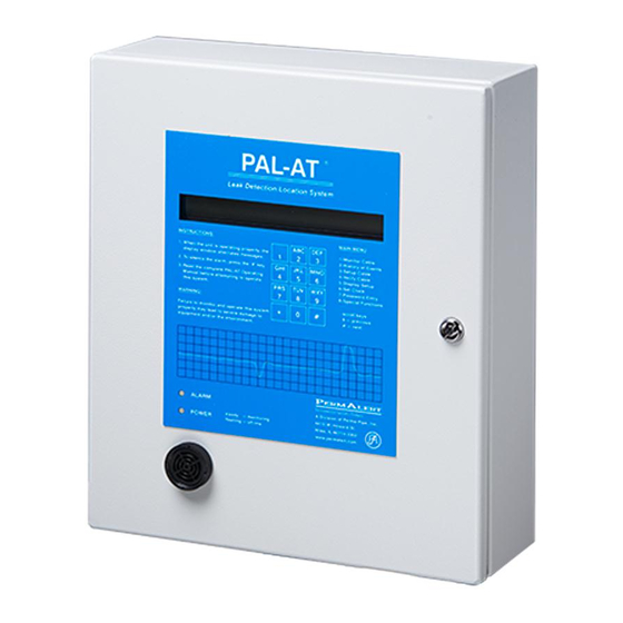
Summary of Contents for Permalert PAL-AT AT30C
- Page 2 NO LIABILITY FOR ANY DAMAGES INCURRED DIRECTLY OR INDIRECTLY FROM ANY TECHNICAL OR TYPOGRAPHICAL ERRORS OR OMISSIONS CONTAINED HEREIN OR FOR DISCREPANCIES BETWEEN THE PRODUCT AND THE MANUAL. IN NO EVENT SHALL PERMALERT BE LIABLE FOR ANY INCIDENTAL, CONSEQUENTIAL, SPECIAL, OR EXEMPLARY DAMAGES, WHETHER BASED ON TORT, CONTACT OR OTHERWISE, ARISING OUT OF OR IN CONNECTION WITH THIS MANUAL OR ANY OTHER INFORMATION CONTAINED HEREIN OR THE USE THEREOF.
-
Page 3: Table Of Contents
PAL-AT Operating Manual Table of Contents Safety Information .................... 4 Introduction ....................5 1.1 Theory of Operation ......................5 1.2 Start Up ..........................5 1.2.1 Installation Instructions ..................5 1.2.2 Initial Display ......................6 1.2.2 Time and Date Format ..................6 1.2.3 LCD Contrast Adjustment ..................6 1.2.3 Manual Updates ....................6 1.2.4... - Page 4 PAL-AT Operating Manual 2.4.4 Alarm Queue ..................... 18 2.4.5 Failure to Enter Monitor Mode ................18 2.5 Display Setup ......................... 19 2.5.1 Multiple Cable System ..................19 2.5.2 Display Setup Data.................... 20 2.5.3 Last Section ...................... 20 2.5.4 Add Sections ..................... 20 2.5.5 Record the Setup Table ..................
- Page 5 PAL-AT Operating Manual 3.2 Types of Alarm Conditions ....................36 3.2.1 Fault ........................36 3.2.2 Break Alarm ....................... 36 3.2.3 Short Alarm ......................36 3.2.4 Drying or Probe Reset Alarm ................36 3.2.5 Leak or Probe Activated Alarm ................36 3.3 Leak Analysis ........................
-
Page 6: Safety Information
PAL-AT Operating Manual Appendix A - Output Relay System ............... 52 A.1 Installation of Output Relay System ................52 A.2 Relay Module Configuration ................... 54 A.3 Internal Diagnostic Indicators ..................55 A.4 Control Relays........................ 55 A.5 RS-232 Port Interface Cable Installation ................ 56 A.6 PAL-AT Control of Output Relay System ............... -
Page 7: Introduction
PAL-AT Operating Manual Introduction Theory of Operation PAL-AT ® uses a pulsed cable-radar technology to detect leaks. PAL-AT sends out low voltage pulses on a cable and monitors reflections received back at the panel. PAL-AT electronically divides the cable into short increments and measures the reflections from each increment. -
Page 8: Initial Display
PAL-AT panel. A power saver feature dims the LCD backlight if a key is not pressed within 5 minutes and the system is not in alarm. 1.2.3 Manual Updates PermAlert is a division of Perma-Pipe, Inc. Refer to the PermAlert web site, www.permalert.com, for the latest revision of this manual. 1.2.4 Wiring Diagrams Figures 1-1 and 1-2 are general wiring diagrams for reference. - Page 9 PAL-AT Operating Manual Figure 1-1 Wiring Diagram for PAL-AT Models AT30C & AT75C...
- Page 10 1 Introduction Figure 1-2 Wiring Diagram for PAL-AT Model AT30K...
-
Page 11: Operating Pal-At
PAL-AT Operating Manual Operating PAL-AT PAL-AT lists the primary functions in the Main Menu. The LCD displays two menu functions at a time. Read the display carefully. PAL-AT prompts for the information it needs. The PAL-AT label has an integral 12-digit keypad to enter 0-9, * and #. -
Page 12: Hydrocarbon Liquids With Zba
2 Operating PAL-AT The baseline is a number between 25 and 35. If the unit displays a value outside this range, it shows a hardware failure. If so, contact PermAlert for assistance. 2.1.4 Hydrocarbon Liquids with ZBA Next PAL-AT displays the message: LCD2.1-04:... -
Page 13: Select Cable Type
Probes are a special case. Probes can be connected to a PAL-AT sensor string anywhere along its length. The maximum number of probes allowed is 10. PermAlert supplies probes with 10 ft [3 m] of jumper cable attached to the input and 50 ft [15 m] to the output of the probe integrator. The probe section length is 60 ft [18 m] for calculating the distance to the end of the section. -
Page 14: No End Found
2 Operating PAL-AT Enter # to accept or * to reenter the distance determined by PAL-AT. The most likely reason this message is displayed is incorrect information (cable type or length) was entered. LCD2.1-10: ENTRY OF ???? IS INVALID - * TO REENTER MUST BE BEYOND SECTION ?? END AT ???? There are two reasons for displaying message LCD2.1-10. -
Page 15: Reference Maps
AGT-Gold sensing cable. The ADJ, or adjustable, setting is reserved for special cases and should only be used after consulting with PermAlert technicians (see section 5.3.4). Enter # to accept the recommended setting or enter * until the preferred setting is displayed and then enter This completes the Setup function. -
Page 16: Reference Issues
2 Operating PAL-AT 2.2.3 Reference Issues Break, Short or No End Found If PAL-AT detects a break, short, or no end of the cable, it does not automatically take a new reference map. These problems must be corrected before a new reference map can be taken. Possible Break Detected A feature of TDR technology is the electrical pulses sent on the cable travel slower when the cable is wet. -
Page 17: Select The Master Map
PAL-AT Operating Manual LCD2.3-01: ENTER CABLE NUMBER (1-4), THEN #: FOR VERIFY * TO EXIT 2.3.2 Select the Master Map PAL-AT prompts to select a map to verify. This is useful to see if the current condition of the cable matches any of the previous maps (see section 3 for further details). -
Page 18: Select To Monitor
2 Operating PAL-AT LCD2.3-08: CABLE ? MATCHES MAP ?, NO END DETECTED BUT SETUP AS ???? FEET. # OR * FOR MENU This message is displayed when the cable is disconnected completely from PAL-AT or it is at least 200 ft [60 m] longer than when it was setup. -
Page 19: Fault Messages Displayed
PAL-AT Operating Manual LCD2.4-04: RECHECKING CABLE “A”, USING MAP “B” * TO RETURN TO MENU “TIME” “DATE” PAL-AT displays this message when it first recognizes a fault condition. PAL-AT rechecks the cable three (3) times during the next few seconds before displaying an actual alarm condition and activating the alarm relays. -
Page 20: Alarm Silence Feature
2.4.5 Failure to Enter Monitor Mode In special cases, PAL-AT may require a master password before it can begin monitoring the first time. The password is unique. Once the password is entered, it is not needed again. Contact PermAlert if the message below is displayed. -
Page 21: Display Setup
PAL-AT Operating Manual display is: LCD2.4-18: ENTER SECURITY PASSWORD * TO CLEAR, # TO ACCEPT ENTRY Enter the master password and #. PAL-AT returns to the Main Menu. Select the monitor function by entering 1#. The message is: LCD2.4-19: MONITORING NOT ENABLED ENTER # TO ENABLE, * TO DISABLE Enter # and PAL-AT returns to the Main Menu. -
Page 22: Display Setup Data
2 Operating PAL-AT 2.5.2 Display Setup Data If a password at level 200 is entered, the next message is: LCD2.5-02: HEREAFTER ENTER # TO SHOW NEXT SECTION OR * TO EXIT OR REENTER SETUP DATA Otherwise it is: LCD2.5-03: HEREAFTER ENTER # TO SHOW NEXT SECTION ENTER * TO RETURN TO MENU Enter * at any time to exit display setup and return to the Main Menu. -
Page 23: Record The Setup Table
Contact PermAlert for details. A record form is provided at the end of this manual to keep a permanent record of the setup table. - Page 24 2 Operating PAL-AT This entry is stored when a sensor string is setup, "A" is the cable number and "B" is the length of the sensor string. LCD2.6-04: CABLE “A” SETUP, WITH LENGTH OF “B” FEET This entry is stored when a new reference or master map is created. "A" is the cable number and "B" is the map number.
- Page 25 PAL-AT Operating Manual LCD2.6-14: FAULT IN FIRST 50 FEET OF CABLE “A” This entry is stored when the cable is disconnected from PAL-AT or additional cable is improperly added to the sensor string. "B" is at least 200 ft [60 m] longer than the sensing string setup length. LCD2.6-15: NO END FOUND IN CABLE "A"...
-
Page 26: History Messages - The Second Line
2 Operating PAL-AT This entry is stored when the clock is reset, "TIME" and "DATE" are the new time and date. LCD2.6-23: TIME RESET TO “TIME”, DATE TO “DATE” This entry is stored when the year is changed using “Set Clock”, or automatically on January 1 of any year. The year is displayed with four digits. -
Page 27: Passwords
PAL-AT Operating Manual Passwords PAL-AT has several security levels. The following table lists the menu functions and required security levels: Security Level Required Menu Function Level 1 – Monitor None 5 - Display setup (read only) 2 – History Silence Alarm 6 - Set Clock 4 –... -
Page 28: Delete Password
2 Operating PAL-AT 2.8.2 Delete Password Follow the steps for messages LCD2.8-01 and LCD2.8-02. If the password entered in LCD2.8-02 is assigned, the message is: LCD2.8-05: FOUND AS ENTRY ??, WITH LEVEL ??? # TO DELETE, * TO RETURN TO MENU Delete this password by entering #. -
Page 29: Select Language
15 seconds to monitor 5,000 ft [1500 m] of cable. This is rarely required, but contact PermAlert for more information to use the special sampling rate. To change the sampling rate, enter 5# for 50 Hz or 6# for 60 Hz interference at the following message. Enter... -
Page 30: Set Noise Factor
2.9.3.3 Set Noise Factor The default setting for this is 63. It is normally used for diagnostic purposes. Do not change it unless directed by a PermAlert technician. Enter # to accept the default entry. LCD2.9-09: ENTER NOISE FACTOR (4-63): 63 * TO CLEAR, # TO ACCEPT ENTRY 2.9.3.4 Set AutoSilence... -
Page 31: Set System Identification And Ethernet Addresses
Enter the 9-digit serial number, omitting any suffix letters. Make sure the serial number is entered correctly. If you have any questions, contact PermAlert Tech Support for assistance. LCD2.9-22: ENTER SYSTEM SERIAL NO.: 321311801... -
Page 32: Enter Phone Number
120 ft. drop back down to 32 and finally rise to 63 at the end. The important point is the leak typically starts where the values start dropping quickly to 20 or less. Contact PermAlert for additional information on data analysis. -
Page 33: Starting Distance
MAPPING MODE-DISABLED FOR TESTS. SELECT * DISABLE MAPPING, # ENABLE MAPPING If mapping is disabled for Test Mode, the initial power up message is changed: LCD2.9-29: PAL-AT LEAK DETECTION *TEST MODE* VX.XX PERMALERT AT30C “TIME” “DATE” 2.10 Communications Options PAL-AT can communicate via several protocols. Simple ASCII commands are used by PALCOM or a customer developed driver. -
Page 34: Palcom 10 Software
2 Operating PAL-AT 2.10.1 PALCOM 10 Software PermAlert offers Windows®-based PALCOM 10 Communication software packages that monitor up to 254 PAL-AT systems 24/7. Refer to the “Communications Options for PAL-AT and LiquidWatch” data sheet or the Palcom 10 User’s Guide for details. -
Page 35: Modbus Rtu, Tcp, And Rtu Over Tcp
PAL-AT Operating Manual Note: If the panel loses power when there are alarms in the alarm queue, the cable status will be “1” (off- line) after power is restored, until the alarm queue is cleared. The reason for this is the system does not change the cable status to “2”... -
Page 37: Ethernet Auto-Negotiate Selection
PAL-AT Operating Manual 2.10.3.3 Ethernet Auto-Negotiate Selection By default, the PAL-AT is shipped with the Ethernet port permanently set to 100Mb / Full duplex. Optionally, the port can be set to auto negotiate speed and duplex when required. This is most often required when hard setting the switch port isn’t possible to allow 100Mb / full duplex, or when connecting to a network that otherwise requires auto negotiation (i.e. -
Page 38: Types Of Alarm Conditions
3 Response to Alarms Computer room subfloors, clean rooms, and pipe tunnels are good examples of accessible locations. The simplest course of action for accessible locations is to check the location. Checking the location means inspecting the sensor at the actual location, not just in the general vicinity. Secondary contained piping and direct buried cable are examples of inaccessible locations. -
Page 39: Leak Analysis
PAL-AT Operating Manual Leak Analysis The procedure to locate a leak depends on whether the leak is at an accessible location or inaccessible location. Menu function 2, History of Events, is used during the analysis to determine where a leak exists. Step through the history archive and record the appropriate data (time, distance and map number) for entries referring to a leak and new reference map. -
Page 40: Repetitive Cycling Alarms
3 Response to Alarms 3.3.4 Repetitive Cycling Alarms There are several possible causes for mixed “leak” and “drying” alarms. Connector Problem An intermittent connection in a cable connector can cause alarms. Causes include: Connectors not tightened together securely. Improperly sanding the “Gold”... -
Page 41: Tests And Maintenance
If it has re-set to 00:00:00 01/01/13 then replace the battery. The battery is 3 V type CR2025. It can be obtained locally or through PermAlert. It is replaceable by gently lifting the retaining clip to remove the old battery and sliding in the new one. -
Page 42: Auxiliary Header
4 Tests and Maintenance Auxiliary Header An 8-position auxiliary header, J4, is located below the AC/DC power switch. Two-pin shunts should only be used for special situations. The shunts should be stored vertically on the right-hand side of the header when not in use, as shown. -
Page 43: Usb Port
The flash drive will contain a folder named with the serial number. For example, serial number 321311801 will have a folder named “32131180.1”. All the data files for that system will be stored in subfolders under it. This data can be sent to PermAlert Technical Support for evaluation. Contact PermAlert Technical Support for further instructions. -
Page 45: Troubleshooting
PAL-AT Operating Manual Troubleshooting Initial Power-Up Checks Warning - Before accessing the PAL-AT panel, the panel must be disconnected from the power source and isolated from any hazardous voltage present in the panel, e.g. relay wiring. Refer to the PAL-AT Installation Manual for wiring instructions. Refer all servicing to qualified personnel. -
Page 46: Dc Voltages
High and Medium when a cable is configured for High sensitivity. A special adjustable setting is available when a custom setup is required, under direction of PermAlert technicians. The scan lights may blink rapidly during a warm-up period if the panel is not monitoring. -
Page 47: Zener Barrier Panel
PAL-AT Operating Manual Zener Barrier Panel A Zener Barrier Panel (ZBP) is required when sensor cables are installed in hazardous locations to limit the energy passing onto the cable. It is mounted adjacent to the PAL-AT panel. A Zener Barrier Assembly (ZBA) is installed in the ZBP and provides a protective circuit between PAL-AT and the ZBP fuse terminals for the sensing string. -
Page 48: Zba External Fuse
The replacement 5x20 mm fuse is rated 250 mA, 250 V, fast-acting. It can be obtained locally or purchase from PermAlert (P/N 8067989). If the ZBA external fuse fails, PAL-AT displays the message "NO END FOUND" or "FAULT IN FIRST 50 FEET". -
Page 49: Troubleshooting Guide
PAL-AT Operating Manual Troubleshooting Guide The following guide lists the most common encountered problems. Also, refer to the PAL-AT Installation Manual for detailed installation information. If you are unable to resolve a problem, contact PermAlert Field Technical Assistance at techsupport@permalert.com or 847-966-2190. -
Page 50: Restrictions & Limitations
Bad cable Test / re-terminate structured cable AT-ORC communications Wrong firmware in AT-ORC (AT-ORC Send AT-ORC in to PermAlert for problems was originally used with older generation firmware upgrade. PAL-AT) Wrong firmware in PAL-AT (versions Upgrade PAL-AT firmware to 1.14... -
Page 51: Probes
5.7.2 Probes 1. The maximum number of probes connected to PAL-AT is 10 for each cable. Consult PermAlert for exceptions. 2. The PHLR probe is resettable after exposure to all fuels, including non-volatile diesel and jet fuel and is recommended for those applications. -
Page 52: Pal-At Setup Record
5 Troubleshooting PAL-AT Setup Record DATE: ______________ MODEL #: ____________________________________________________ SERIAL #: ____________________________________________________ LOCATION: ___________________________________________________ CABLE DATA SECTION DATA Section # Length Counts Type Length Counts... - Page 53 PAL-AT Operating Manual CABLE DATA SECTION DATA Section # Length Counts Type Length Counts...
-
Page 54: Appendix A - Output Relay System
PAL-AT Operating Manual Appendix A - Output Relay System The PAL-AT Output Relay System consists of an electronic microprocessor-based interface and control panel that monitors a PAL-AT Leak Detection/Location System and controls from 4 to 60, 10-amp 250-volt rated relays. The output relays are available in groups of 4. There are four PAL-AT Output Relay System components available: Model Description... - Page 55 PAL-AT Operating Manual Figure A-1 - AT-ORC Output Relay Controller Wiring Diagram Figure A-2 – AT-ORx4 Output Relay Panel Wiring Diagram...
-
Page 56: Relay Module Configuration
Output Relay System Figure A-3: AT-ORx1 Output Relay Panel Wiring Diagram Relay Module Configuration Each added AT-RM relay module must be configured before operating the system. Two jumpers are set to select the numbers assigned to the 4 relays (1-4, 5-8, etc.). Locate the jumpers in the lower right corner. The 60 relays are organized in 15 banks of 4. -
Page 57: Internal Diagnostic Indicators
PAL-AT Operating Manual Jumper Setting vs. Relay Number Assignment Relay Bank 33-60 / 1-32 Relay Number Assignment Select 1-32 Relay 5 Relay 6 Relay 7 Relay 8 1-32 Relay 9 Relay 10 Relay 11 Relay 12 1-32 Relay 13 Relay 14 Relay 15 Relay 16 1-32... -
Page 58: Rs-232 Port Interface Cable Installation
Output Relay System RS-232 Port Interface Cable Installation The AT-ORC Output Relay Controller is provided with an RS-232 communications port and an interface cable. The 9-pin male D connector on the interface cable connects to the Output Relay Controller RS-232 port. -
Page 59: Change Output Relay Assignments
PAL-AT Operating Manual When # is entered, the relay data can be viewed for the first section: LCDA-03: CABLE ?, SECTION ?? ACTIVATES RELAY ?? * FOR MENU, # FOR NEXT SECTION In a similar manner, the data for each section is displayed. The PAL-AT returns to the Main Menu after all sections are displayed. -
Page 60: Warranty
Warranty Seller warrants that the PermAlert Leak Detection System (the "System") will be free from defects in materials and workmanship for a period of twelve (12) months from the date of first use of the System or eighteen (18) months from the date of shipment by Seller to Buyer of the System;... - Page 62 ©2018, PERMA-PIPE, Inc. All Rights Reserved. (8/15) PA 2001 REV. 08...
Need help?
Do you have a question about the PAL-AT AT30C and is the answer not in the manual?
Questions and answers