Sign In
Upload
Manuals
Brands
Patton electronics Manuals
Network Router
OnSite 2800 Series
Patton electronics OnSite 2800 Series Manuals
Manuals and User Guides for Patton electronics OnSite 2800 Series. We have
2
Patton electronics OnSite 2800 Series manuals available for free PDF download: User Manual, Quick Start Manual
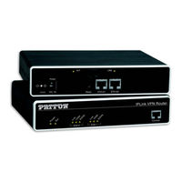
Patton electronics OnSite 2800 Series User Manual (135 pages)
Managed VPN Router
Brand:
Patton electronics
| Category:
Network Router
| Size: 1 MB
Table of Contents
User Manual
1
Summary Table of Contents
3
Table of Contents
4
List of Figures
10
List of Tables
11
About this Guide
12
Audience
12
Structure
12
Precautions
13
Safety When Working with Electricity
14
General Observations
15
Typographical Conventions Used in this Document
16
General Conventions
16
General Information
17
Chapter 1 General Information
18
Onsite Model 2800 Series Overview
18
Onsite Managed VPN Router (2805 Shown)
18
Onsite 2800 Series Detailed Description
19
Onsite 2800 Series Model Codes
19
Serial WAN Models
19
Onsite 2800 Series X.21, and V.35 Connectors
19
Ethernet WAN Models
20
Onsite 2800 Series 10Base-T Ethernet Port Connectors
20
Model Code Extensions
21
Onsite 2800 Series Power Input Connectors
21
Ports Descriptions
22
Onsite 2800 Series Front Panels
22
Rear Panel Ports
22
Applications Overview
23
Branch-Office Virtual Private Network over Frame Relay Service
23
Branch-Office Virtual Private Network over a Frame-Relay Service Network
23
Corporate Multi-Function Virtual Private Network
24
Hardware Installation
26
Chapter 2 Hardware Installation
27
Planning the Installation
27
Installation Checklist
28
Site Log
29
Network Information
29
Network Diagram
29
IP Related Information
29
Software Tools
29
Power Source
29
Sample Site Log Entries
29
Location and Mounting Requirements
30
Installing the VPN Router
30
Connecting Cables
30
Installing the Ethernet Cable
30
Mounting the VPN Router
30
Installing the Serial WAN Cable
31
Connecting an Onsite 2800 Series Device to a Hub
31
Ethernet 10/100Base-T (RJ-45) Port Pin-Outs
31
Installing the V.35 Interface Cable
32
Rear View of the Router Showing Location of V.35 Interface Connector
32
Signal Pin-Outs for the V.35 Interface on the Onsite 2800
32
Installing the X.21 Interface Cable
33
Rear View of the Router Showing Location of X.21 Interface Connector
33
Installing the T1/E1 Twisted Pair Cables
34
Rear Panel of 2803K/EUI
34
Rear Panel of 2803T/EUI
34
Signal Pin-Outs for the X.21 Interface on the Onsite 2800
34
RJ-48C Receptacle
34
Installing the E1 Dual Coaxial Cables
35
Rear Panel of 2803K/UI
35
Connecting to External Power Source
36
Power Connector Location on Rear Panel
36
VPN Router Front Panel Leds and Console Port Locations (Onsite 2835 Shown)
37
Getting Started with the Onsite Managed VPN Router
38
Introduction
39
Steps for Setting up a New Onsite VPN Router
39
Configure IP Address
40
Connect with the Serial Interface
40
Power Connection and Default Configuration
40
Connecting to the Terminal
40
Factory Default IP Address and Network Mask Configuration
40
Changing the IP Address
41
Login
41
Connect the Onsite VPN Router to the Network
42
Load Configuration
42
Connecting the Onsite VPN Router to the Network
42
Serial Port Configuration
44
Chapter 4 Serial Port Configuration
45
Introduction
45
Serial Port Configuration Task List
45
Disabling an Interface
45
Enabling an Interface
46
Configuring the Encapsulation for Frame Relay
47
Enter Frame Relay Mode
48
Configuring the LMI Type
48
Configuring the Keep-Alive Interval
49
Entering Frame Relay PVC Configuration Mode
49
Configuring the PVC Encapsulation Type
50
Binding the Frame Relay PVC to IP Interface
50
IP Interface Wan Is Bound to PVC 1 on Port Serial 0 0
51
Enabling a Frame Relay PVC
52
Disabling a Frame Relay PVC
52
Displaying Serial Port Information
53
Displaying Frame Relay Information
54
Integrated Service Access
55
Typical Integrated Service Access Scenario with Dedicated Pvcs
55
IP Context with Logical IP Interfaces Bound to Ethernet Port, Serial Port PVC 1 and PVC 2
56
T1/E1 Port Configuration
58
Chapter 5 T1/E1 Port Configuration
59
Introduction
59
T1/E1 Port Configuration Task List
59
Enable/Disable T1/E1 Port
59
Configuring T1/E1 Port-Type
60
Configuring T1/E1 Clock-Mode
60
Configuring T1/E1 Line-Code
60
Configuring T1/E1 Framing
61
Configuring T1/E1 Line-Build-Out (T1 Only)
61
Configuring T1/E1 Used-Connector (E1 Only)
61
Configuring T1/E1 Application Mode
62
Configuring T1/E1 LOS Threshold
62
Configuring T1/E1 Encapsulation
62
Create a Channel-Group
62
Configuring Channel-Group Timeslots
63
Configuring Channel-Group Encapsulation
63
Entering HDLC Configuration Mode
63
Configuring HDLC CRC-Type
64
Configuring HDLC Encapsulation
64
T1/E1 Configuration Examples
64
Example 1: Frame Relay Without a Channel-Group
65
Example 2: Framerelay with a Channel-Group
66
Example 3: PPP Without a Channel-Group
66
Example 4: PPP with a Channel-Group
66
VPN Configuration
67
Chapter 6 VPN Configuration
68
Introduction
68
Authentication
68
Encryption
68
Transport and Tunnel Modes
69
VPN Configuration Task List
69
Creating an Ipsec Transformation Profile
69
Creating an Ipsec Policy Profile
70
Creating/Modifying an Outgoing ACL Profile for Ipsec
72
Configuration of an IP Interface and the IP Router for Ipsec
73
Displaying Ipsec Configuration Information
73
Debugging Ipsec
74
Sample Configurations
75
Ipsec Tunnel, des Encryption
75
Onsite Configuration
75
Cisco Router Configuration
76
Ipsec Tunnel, AES Encryption at 256 Bit Key Length, AH Authentication with HMAC-SHA1-96
76
Onsite Configuration
76
Cisco Router Configuration
77
Ipsec Tunnel, 3DES Encryption at 192 Bit Key Length, ESP Authentication with HMAC-MD5-96
77
Onsite Configuration
77
Access Control List Configuration
79
Chapter 7 Access Control List Configuration
80
Introduction
80
About Access Control Lists
80
What Access Lists Do
80
Why You Should Configure Access Lists
80
When to Configure Access Lists
81
Features of Access Control Lists
81
Using Traffic Filters to Prevent Traffic from Being Routed to a Network
81
Access Control List Configuration Task List
82
Mapping out the Goals of the Access Control List
82
Adding a Filter Rule to the Current Access Control List Profile
83
Creating an Access Control List Profile and Enter Configuration Mode
83
Adding an ICMP Filter Rule to the Current Access Control List Profile
85
Adding a TCP, UDP or SCTP Filter Rule to the Current Access Control List Profile
87
Binding and Unbinding an Access Control List Profile to an IP Interface
89
Debugging an Access Control List Profile
90
Displaying an Access Control List Profile
90
Examples
92
Denying a Specific Subnet
92
Deny a Specific Subnet on an Interface
92
Link Scheduler Configuration
93
Chapter 8 Link Scheduler Configuration
94
Introduction
94
Configuring Access Control Lists
94
Configuring Quality of Service (Qos)
95
Applying Scheduling at the Bottleneck
95
Using Traffic Classes
95
IP Context and Related Elements
95
Introduction to Scheduling
96
Priority
96
Weighted Fair Queuing (WFQ)
96
Packet Routing in Onsite
96
Shaping
97
Burst Tolerant Shaping or Wfq
97
Hierarchy
97
Quick References
98
Setting the Modem Rate
98
Example of Hierarchical Scheduling
98
Command Cross Reference
99
Link Scheduler Configuration Task List
99
Defining the Access Control List Profile
100
Packet Classification
100
Elements of Link Scheduler Configuration
100
Creating an Access Control List
101
Scenario with Web Server Regarded as a Single Source Host
101
Creating a Service Policy Profile
102
Structure of a Service-Policy Profile
103
Specifying the Handling of Traffic-Classes
104
Defining Fair Queuing Weight
104
Defining Absolute Priority
105
Defining the Bit-Rate
105
Defining the Maximum Queue Length
105
Specifying the Type-Of-Service (TOS) Field
105
Specifying Differentiated Services Codepoint (DSCP) Marking
106
Specifying the Precedence Field
106
TOS Values and Their Meaning
106
Specifying Layer 2 Marking
107
Traffic Control Info (TCI) Field
107
Defining Random Early Detection
108
Discarding Excess Load
108
Devoting the Service Policy Profile to an Interface
109
Using a Service Policy Profile on an IP Interface
109
Displaying Link Arbitration Status
110
Displaying Link Scheduling Profile Information
110
Enable Statistics Gathering
110
Values Defining Detail of the Queuing Statistics
111
Leds Status and Monitoring
112
Status Leds
113
Examples of Onsite 2800 Series Front Panels
113
Onsite LED Indications
113
Contacting Patton for Assistance
114
Chapter 10 Contacting Patton for Assistance
115
Introduction
115
Contact Information
115
Patton Support Headquarters in the USA
115
Alternate Patton Support for Europe, Middle Ease, and Africa (EMEA)
115
Warranty Service and Returned Merchandise Authorizations (Rmas)
115
Warranty Coverage
115
Warranty Service and Returned Merchandise Authorizations
115
Out-Of-Warranty Service
116
Return for Credit Policy
116
Returns for Credit
116
RMA Numbers
116
Shipping Instructions
116
A Compliance Information
118
Compliance
118
Emc
118
PSTN Regulatory
118
Safety
118
Radio and TV Interference (FCC Part 15)
118
CE Declaration of Conformity
118
Authorized European Representative
119
FCC Part 68 (ACTA) Statement (Model 2803 Only)
119
Industry Canada Notice (Model 2803 Only)
119
Appendix B Specifications
121
Ethernet Interfaces
121
Sync Serial Interface
121
T1/E1 Interface (Model 2803 Only)
121
PPP Support
121
IP Services
122
Management
122
Operating Environment
122
Operating Temperature
122
Operating Humidity
122
System
122
Dimensions
122
Power Supply
123
Internal AC Version
123
12VDC Version with External AC Power Adapter (Models 2802, 2821, 2835)
123
5VDC Version with External Power Adapter (Model 2805)
123
12VDC Version with External AC Power Adapter
123
(Models 2802, 2821, 2835)
123
B Specifications
121
Cabling
124
Introduction
125
Serial Console
125
Connecting a Serial Terminal
125
Ethernet 10Base-T and 100Base-T
126
Ethernet Cross-Over
126
Ethernet Straight-Through
127
Appendix D Port Pin-Outs
129
Introduction
129
Console Port, RJ-45, EIA-561 (RS-232)
129
Console Port
129
RS-232 Console Port
129
Ethernet 10Base-T and 100Base-T Port
130
Sync Serial Port
130
V.35 Serial Port
130
Serial Port
131
X.21 Female DB-15 Connector
131
D Port Pin-Outs
129
EIA-561 (RJ-45 8-Pin) Port
129
Onsite 2800 Series Factory Configuration
132
Introduction
133
Installation Checklist
134
Introduction
135
Installation Checklist
135
Advertisement
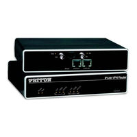
Patton electronics OnSite 2800 Series Quick Start Manual (9 pages)
2800 Series VPN Routers
Brand:
Patton electronics
| Category:
Network Router
| Size: 0 MB
Table of Contents
Quick Start Guide
1
Setting the Ip Address
3
Changing the Ip Address
4
Connecting to the Network
5
Additional Information
6
EC Declaration of Conformity
7
Copyright Statement
8
Patton Support Headquarters in the Usa
8
Advertisement
Related Products
Patton electronics IPLink 2803
Patton electronics IPLink 2821
Patton electronics IPLink 2835
Patton electronics IPLink 2823
Patton electronics 2888
Patton electronics IPLink 2802
Patton electronics IPLink 2805
Patton electronics OnSite 2803/K
Patton electronics OnSite 2803/T
Patton electronics 2121
Patton electronics Categories
Modem
Network Hardware
Network Router
Media Converter
Extender
More Patton electronics Manuals
Login
Sign In
OR
Sign in with Facebook
Sign in with Google
Upload manual
Upload from disk
Upload from URL