Sign In
Upload
Manuals
Brands
Parker Manuals
DC Drives
638 series
Parker 638 series Servo Drive/Controller Manuals
Manuals and User Guides for Parker 638 series Servo Drive/Controller. We have
1
Parker 638 series Servo Drive/Controller manual available for free PDF download: Product Manual
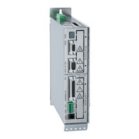
Parker 638 series Product Manual (129 pages)
Digital Servo Drive
Brand:
Parker
| Category:
Servo Drives
| Size: 14 MB
Table of Contents
Table of Contents
4
The most Important Thing First
8
Safety Precautions
9
General Information
11
System Description
11
Special Features of the 638 Servo Drive
11
Overview of Standard Digital Communication
11
Determining Criteria for the Utilization of the 638 Drive
12
Operation Configuration
12
Model Code
13
Combination Possibilities for the Various Communication / I/O - Modules
14
Module Slots Layout
15
Module Design
15
Packaging, Transport, Storage
16
Dimensions
17
638A Series
17
Series
18
Insulation Concept
19
Overview of Compact Unit Connections
20
638A01
20
638B03
21
Assignments Power Connections
22
Power, Ballast, DC Bus - Connection X60
22
Control Supply Voltage X01
22
Motor - Connection X61
22
Brake / Thermo - Connection X62
23
Feedback Sensor X30
24
Feedback - Module X300
24
Feedback Connection X30 (SUB D 09 Socket)
25
Feedback - Module X300 with Memory
27
Service-Interface COM1 (RS232)
28
Safe Torque off
29
Connection Safe Torque off X11
29
Connection WITHOUT the Utilization of the Safe Torque Off, (STO), Function
29
Signal Connection
30
Control Signal Plug X10 (SUB D25 Socket)
30
Multi-Function X40
31
Incremental - Output
32
Incremental - Input
32
Stepper Motor Input
33
SSI-Encoder Interface
34
Fieldbus Interface COM2
35
Pinning for RS232
35
Pinning for RS422/485
35
Pinning for CAN
36
Pinning for Profibus DP
36
Pinning for EA5 I/O-Interface (Digital in and Outputs)
36
Fieldbus Interface COM2 in Combination with COM3 (OPTION SLOT A/B)
37
Pinning for Interbus S (RP IBS)
37
Fieldbus Interface RP 2CA, 2C8
38
Pinning CAN1-BUS and CAN2-BUS
38
Pinning RP 2C8 X120 (with I/O's)
38
DIP Switch Position for Option Module RP 2CA and RP 2C8
39
Fieldbus Interface RP CCA, CC8
40
Pinning CAN1-BUS, CAN2-BUS and RS485
40
Pinning RP CC8 X120 (with I/O's)
40
DIP Switch Position for Option Module RP CCA and RP CC8
41
Fieldbus Interface RP PCA, PC8
42
Pinning Profibus DP and CAN2-BUS and RS485
42
Pinning RP PC8 / X120 (with I/O's)
42
EN-V1215.Doc / Type
42
DIP Switch Position for Option Module RP PCA, PC8
43
2.14 Overview of the Terminal Cross Section
44
Operating Mode
45
Operating Mode General
45
Operating Modes and Pin Functions
46
Configurable Pin Functions (Operating Mode Dependent)
47
Functions Diagrams with Protection Mode "Switch off
48
Mechanical Installation
50
Mounting
50
Cautionary Markings
50
Control Cabinet Mounting
50
Cooling and Ventilation
50
Electrical Installation
51
Installation General
51
Safety
51
Danger of Electric Shock
51
Dangerous Areas
51
Grounding - Safety Grounding
51
Ground Connections
51
Short-Circuit Capacity and Discharge Currents
51
Power Mains Connection
52
Types of Power Mains
52
Mains Supply Voltage Range 638A
52
Mains Supply Voltage Range 638B
52
Protective Ground Connection (PE)
52
Cable Cross Section
52
Dimensioning of Power Mains Cable and the Over-Current Protection
52
Fault Current Protection
54
DC Link Parallel Connection
55
General
55
Variation 1; Servo Drives Without DC LINK Protection
55
Variation 2; Servo Drives with DC LINK Protection
58
Function Softstart
61
Installation Instructions and Warnings
61
Layout of the Ballast Capacity
62
Fuses , Contactors
63
Brake Resistor
64
Selection of the Brake Resistor
64
Configuration of the Brake Resistor
65
Wiring Instructions
67
Electromagnetic Compatibility (EMC)
67
Hints for Mounting
67
Example for Mounting
68
Hardware Configuration
69
Jumpers
69
Power Board Layout Plan 638A
70
Power Board Layout Plan 638B
70
Commissoning
72
Commissioning Preparation
72
Step : Wiring and Communications Test
73
Step . :Feedback Test and Motor Selection
74
Step 2.2 Motor Selection
74
Step 2.3 Motor with Resolver Feedback
76
Step 2.4 Motor with HIPERFACE Feedback
76
Step 2.5 Motor with SIN-COS Feedback Linear Motor
76
Step : Power up and Drive Activation
77
Step 3.1 Power up
77
Step 3.2 Drive Activation
77
Step : Control Loop Optimization
78
Step 4.1 Control Loop Optimization with Rotary Motors
78
Step : Operation Mode Selection
79
Step Fieldbus Interface
80
Step
81
Data Save
81
Step : Data Save
81
Safe Torque off (STO)
83
General Introduction
83
Important Technical Terms and Explanations
83
Stop Category According to en 60204-1 (Chapter. 9.2.2)
83
Applications in Accordance with the Regulations
84
Trained Personnel
84
Benefits with the Employment of the Safe Torque off Function
84
Safety Instructions and Limitations
85
Safe Torque off Function, (STO)
86
Block Circuit Diagram
86
Status Diagram and Function of Terminals STO1# und STO2
87
Configuration and Parameter Settings
88
Application Example of STO (Safe Torque Off)
93
Application Example 1
94
Application Example 2
95
Application Example 3
96
Application Example 4
97
STO Function Test
98
Signal Inputs Technical Data - Terminal Connection X11
100
Diagnosis and Trouble-Shooting
101
7-Segment-Display
101
Reset of a Drive Trouble
106
Trouble-Shooting
107
Standards and Certifications
108
Compliance with Regulations, Limitations and Basic Conditions
108
Conditions of Utilization for UL Certification 638A
109
11.3 Conditions of Utilization for UL Certification 638B
110
Technical Data
111
General Technical Data
111
Power Circuit
111
Control Circuit
111
Signal Inputs and Outputs - Connection X10
111
EN-V1215.Doc / Type
111
Analog - Outputs
112
Thermo-Control X30
112
Thermo-Control X62
112
Brake-Control X62
112
Signal Inputs and Outputs - Connection X120B Resp. 120C
113
Digital Control
113
Digital Communication
114
X30 Resolver Evaluation / Transmitter Principles
114
X30 Endat Evaluation
115
Controller System
115
Mechanical Data
115
Technical Unit Data
116
116
116
Output Power 638A
117
Singlephase and Threephase Supply
117
118
118
Output Power 638B
119
Software
121
EASYRIDER Windows - Software
121
13.2 Introduction BIAS Editor
122
Program Layout
123
Execute a BIAS Program
123
Execute a PLC Program
124
Execute a Mathematics Program
124
BIAS - Commands
125
Appendix
126
STO - Safety - Parameter - Report - Proposal
126
Memo
127
Modification Record
128
EN-V1215.Doc / Type
129
Advertisement
Advertisement
Related Products
Parker 63AD
Parker 63AC/O
Parker 631 Series
Parker 64ACX
Parker 61AC/O
Parker 6K8
Parker 650G Frame 3
Parker 6911
Parker 6053-LNET-00 TechBox
Parker 660 Series
Parker Categories
Controller
Control Unit
Industrial Equipment
Dryer
DC Drives
More Parker Manuals
Login
Sign In
OR
Sign in with Facebook
Sign in with Google
Upload manual
Upload from disk
Upload from URL