Sign In
Upload
Manuals
Brands
PANHANS Manuals
Power Tool
245/10
PANHANS 245/10 Manuals
Manuals and User Guides for PANHANS 245/10. We have
2
PANHANS 245/10 manuals available for free PDF download: Operating Manual
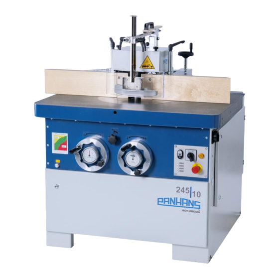
PANHANS 245/10 Operating Manual (71 pages)
Tilting Spindle Moulders / Table Milling Machines
Brand:
PANHANS
| Category:
Power Tool
| Size: 4.13 MB
Table of Contents
Table of Contents
2
Introduction
7
Legal Notice
7
Illustrations
7
Symbols
7
General Symbols
7
Figure 1: Milling Arbor with Cutter Head
7
Symbols in Safety Instructions
8
General
9
Positioning with the Ultimo Touch 300 Controller
9
Intended Use
10
Target Group and Previous Experience
10
Requirements for the Operators
10
Accident Prevention
11
General Safety Regulations
11
Included Components
12
Optional Accessories
12
Safety
13
Basic Safety Instructions
13
Application Area and Intended Use
13
Modifications and Conversions to the Machine
13
Permissible Tool Dimensions
14
Residual Risks
14
Observe the Environmental Protection Regulations
15
Organisational Measures
15
Personnel Selection and Qualification - Basic Duties
16
Safety Instructions for Specific Phases of Operation
16
Before Working
16
Normal Operation
17
Special Work Within the Scope of Maintenance Work as Well as Troubleshooting in the Workflow
18
After Work
18
Safe Working Practices
18
Operator Training
18
Stability
18
Setting up and Adjusting the Machine
18
Tool Handling
19
Tool Clamping
19
Setting the Milling Fence
19
Direction of Rotation
19
Speed Selection
19
Machine Operation and Selection / Adjustment of Protective Devices
19
Use of Work Devices with Protective Function
21
Noise Reduction
21
Standard Safety Equipment
21
Optional Safety Equipment
21
Hazardous Areas
22
Machine Data
23
Technical Specifications
23
Figure 2: Nameplate
23
Workstation
24
Emission Levels
24
Noise Information
24
Noise Emission Values
24
Figure 3: Working Area
24
Dimensions
25
Without Table Extensions (Standard)
25
With Table Extensions (Option)
25
Figure 4: Dimensions Without Table Extensions
25
Figure 5: Dimensions with Table Extensions
25
Installation and Connection
26
Check Delivery Conditions
26
Transport to the Installation Site
26
Installing the Machine
26
Figure 6: Transport Pallet
26
Temporary Storage
27
Lashing on a Transport Vehicle
27
Figure 7: Lashing Points (4 X)
27
Connecting the Extraction Unit
28
Air Speed
28
Existing Negative Pressure at 20 M/S
28
Figure 8: Suction Nozzles
28
Electrical Connection
29
Back-Up Fuses (On-Site)
29
Machine Socket
29
Figure 9: Terminal Box
29
Figure 10: Machine Socket
29
Components and Control Elements
30
Figure 11: Components and Control Elements
30
Commissioning
31
Switching on and off
31
Rotational Direction
31
Switch on the Milling Spindle
31
Switch off the Milling Spindle
31
Figure 12: Warning "Climb Milling Mode
31
Emergency Stop Functions
32
Tool Change
32
With Quick Clamping Device (Standard)
32
Figure 13: Emergency Stop Push Buttons
32
Figure 14: Milling Arbor with Quick Clamping Device
32
Figure 15: Marking for Upper Spacer Ring
32
With HSK 80 Tool Changing System (Option)
33
Changing Procedure
33
Figure 16: Remove Dust Protection Cap
33
Figure 17: Loosen & Remove the Milling Arbor with Spanner
33
Figure 18: Remove Milling Arbor
33
Figure 19: Clamping Surfaces and Locking
33
With HSK 63 and HSK 85 Tool Changers (Option for 245|200 and 300)
34
Figure 20: Storage Tray for Pin Spanner
34
Figure 21: Detached Clamping Cartridge with Milling Arbor
34
Positioning the Tool Height and Tool Angle
35
Speed Setting
36
Version 245|100
36
Versions 245|200 and 245|300
36
Cutting Speed Chart
36
Figure 22: Lever to Release the V-Belt
36
Figure 23: Cutting Speed Chart
36
Milling Fences
37
Placing and Aligning the Milling Fence
37
Figure 24: Locking Bolts and Detent Holes
37
Figure 25: Move Centrally over Milling Spindle
37
Figure 26: Align Dovetail Receptacle to Locking Pin
37
Figure 27: Lock and Engage
37
Functions and Adjustment of the Milling Fences
38
Fence Type 301
38
Figure 28: Operating Elements Fence Type 301
38
Figure 29: Locking Bolt of Type 301
39
Fence Type 302
40
Figure 30: Operating Elements Fence Type 302
40
Figure 31: Locking Bolt of Type 302
40
Figure 32: Clamping Screws
41
Handwheel Adjustment for Types 301 and 302
42
Figure 33: Handwheel „Target Reached
42
Figure 34: Handwheel Battery Change
43
Fence Type 311
44
Figure 35: Operating Elements Fence Type 311
44
Figure 36: Locking Bolt of Type 311
44
Fence Type 320
45
Figure 37: Operating Elements Fence Type 320
45
Figure 38: Locking Bolt of Type 320
46
Figure 39: Clamping Screws
46
Ring Fence TAPOA 1639
47
Figure 40: Operation Elements of the Ring Fence TAPOA 1639
47
Figure 41: TAPOA 1639 Ring Fence Adjustment
47
Protection and Pressure Devices
48
TYPE 1629 GAMMA V (Standard)
48
TYPE 1624 CENTREX (Option)
48
Figure 42: Protection and Pressure Device 1629 GAMMA V
48
Figure 43: Protection and Pressure Device 1624 CENTREX
48
Optional Components
49
Integral Fence System
49
Operation and Functions
49
Figure 44: Integral Fence System (Option)
49
Figure 45: Integral Fence System - Operation and Functions
49
Figure 46: Optional Table Slide
49
Safety Rulers for the Milling Fence
50
Swivel-Away Device for the Milling Fence
50
Turntable (360 Degrees) for the Milling Fence
50
Figure 47: Safety Ruler Set
50
Figure 48: Swivel-Away Device
50
Figure 49: Turntable with Opening for Clamping
50
Extendable Frame Support
51
TM 300 - RFID Based Machine Access Control System
51
Calibration Unit "Zeromaster
51
Figure 50: Clamping Lever for Extendable Frame Support
51
Figure 51: TM-300 Machine Access Control System
51
Figure 52: Calibration Unit "Zeromaster
51
Tenoning and Slotting Device Type 1376
52
Operation
52
Figure 53: Tenoning Guard 1376
52
Figure 54: Angle Ranges (Position of the Screws)
52
Adaptation to the Machine Table (Only Required for Retrofitting)
53
Supplementary Protective Cover 1641 (Option)
53
Kickback Guard Type 1648
53
Figure 55: Adapt Tenoning Device (Drilling Sketch)
53
Figure 56: Kickback Guard Type 1648
53
Cross-Cut Fence LAS-M
54
Extension for Cross-Cut Fence LAS-M
54
Roller Table
54
Figure 57: Length Stop LAS-M
54
Figure 58: Roller Table
54
Power Feeders
55
Consoles for Power Feeders
55
Figure 59: Power Feeder Type PV84
55
Figure 60: Power Feeder Type Variomatic 4N
55
Figure 61: Console Rigid
55
Figure 62: Console Movable
55
Troubleshooting
56
Maintenance and Inspection
57
Maintenance of the Milling Fence
57
Maintenance of the Tenoning and Slotting Device Type 1376 (Option)
57
Readjust the Motor Brake on Version 245|100
58
Check the Adjustment
58
Replace Motor Brake
58
Motor Brake on 245|200 and 245|300
58
Figure 63: Adjusting Screw of the Motor Brake
58
Maintenance Plan
59
Change and Tighten the Drive Belt
60
Version 245|100
60
Version 245|200 and 245|300
60
Figure 64: Tightening Drive Belt (245|100)
60
Figure 65: Tightening Drive Belt (245|200 and 245|300)
60
Checking the Drive Belt Tension
61
Figure 66: Checking the Belt Tension
61
Lubrication Instruction
62
Change Lubricator
62
Figure 67: Change Lubricator
62
Figure 68: Activation with Activation Screw
62
Lubrication Plan
63
Figure 69: Lubrication Points on the Machine
63
Figure 70: Central Lubrication
63
Options and Accessories
64
Technical Extensions
64
Milling Fences
65
Milling Spindles and Arbors
66
Roller Table, Cross-Cut Fence and Tenoning Device
68
Power Feeders and Consoles
68
Special Accessories
69
Disassembly and Scrapping
70
EU - Declaration of Conformity
71
Advertisement
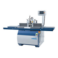
PANHANS 245/10 Operating Manual (61 pages)
Table Milling Machine
Brand:
PANHANS
| Category:
Power Tool
| Size: 3.12 MB
Table of Contents
Table of Contents
2
Introduction
7
Legal Notice
7
Illustrations
7
Symbols
7
General Symbols
7
Symbols in Safety Instructions
8
General
9
Intended Use
10
Target Group and Previous Experience
10
Requirements for the Operators
10
Accident Prevention
11
General Safety Regulations
11
Included Components
12
Optional Accessories
12
Safety
13
Basic Safety Instructions
13
Application Area and Intended Use
13
Modifications and Conversions to the Machine
13
Permissible Tool Dimensions
14
Residual Risks
14
Observe the Environmental Protection Regulations
15
Organisational Measures
15
Personnel Selection and Qualification - Basic Duties
16
Safety Instructions for Specific Phases of Operation
16
Before Working
16
Normal Operation
17
Special Work Within the Scope of Maintenance Work as Well as Troubleshooting in the Workflow
18
After Work
18
Safe Working Practices
18
Operator Training
18
Stability
18
Setting up and Adjusting the Machine
18
Tool Handling
19
Tool Clamping
19
Setting the Milling Fence
19
Direction of Rotation
19
Speed Selection
19
Machine Operation and Selection / Adjustment of Protective Devices
19
Use of Work Devices with Protective Function
21
Noise Reduction
21
Standard Safety Equipment
21
Optional Safety Equipment
21
Hazardous Areas
22
Machine Data
23
Technical Specifications
23
Figure 1: Nameplate
23
Working Area
24
Emission Levels
24
Noise Information
24
Noise Emission Values
24
Figure 2: Working Area
24
Dimensions
25
Front View
25
Top View 1
25
Top View 2
25
Figure 3: Dimensions - Front View
25
Figure 4: Dimensions - Top View 1
25
Figure 5: Dimensions - Top View 2
25
Installation and Connection
26
Check Delivery Conditions
26
Transport to the Installation Site
26
Installing the Machine
26
Figure 6: Transport Pallet
26
Temporary Storage
27
Lashing on a Transport Vehicle
27
Figure 7: Lashing Points (4 X)
27
Connecting the Extraction Unit
28
Air Speed
28
Existing Negative Pressure at 20 M/S
28
Figure 8: Suction Nozzles
28
Electrical Connection
29
Back-Up Fuses (On-Site)
29
Machine Socket
29
Figure 9: Terminal Box
29
Figure 10: Machine Socket
29
Components and Control Elements
30
Figure 11: Components and Control Elements
30
Commissioning
31
Switching on and off
31
Rotational Direction Switch
31
Switching the Spindle on and off
31
Figure 12: Main Switch
31
Figure 13: Control Panel
31
Emergency Stop Function
32
Service Door with Safety Switch
32
Figure 14: Unlock Service Door
32
Figure 15: Lock Service Door
32
Speed Setting
33
Cutting Speed Chart
33
Figure 16: Lever to Release the V-Belt
33
Figure 17: Cutting Speed Chart
33
Tool Change
34
With Quick Clamping Device (Standard)
34
Figure 18: Milling Arbor with Quick Clamping Device
34
Figure 19: Marking for Upper Spacer Ring
34
Position the Milling Spindle
35
Height Adjustment
35
Tilt Adjustment
35
Zero-Degree Lock
35
Figure 20: Handwheels for Height / Tilt Adjustment
35
Milling Fences
36
Placing and Aligning the Milling Fence
36
Figure 21: Locking Bolts and Detent Holes
36
Figure 22: Move Centrally over Milling Spindle
36
Figure 23: Align Dovetail Receptacle to Locking Pin
36
Figure 24: Lock and Engage
36
Functions and Adjustment of the Milling Fences
37
Fence Type 215 (Standard)
37
Figure 25: Operating Elements Fence Type 215
37
Fence Type 216 (Option)
38
Operating the Fences
38
Fence Plate Adjustment
38
Folding up the Protective Hood
38
Fit a Grooved Board or Safety Rulers
38
Figure 26: Operating Elements Fence Type 216
38
Figure 27: Locking Bolt of Type 301
38
Tool Covers for High Milling Arbors
39
Lifting off and Removing the Fence
39
Swivel-Away Device Type 219 (Option)
39
Swivel Away the Milling Fence
39
Figure 28: Hydraulic Swivel-Away Device
39
Handwheel Adjustment for Type 216 (Option)
40
Handwheel Battery Change
40
Figure 29: Digital Handwheel
40
Figure 30: Battery Change
40
Ring Fence TAPOA 1639
41
Figure 31: Operation Elements of the Ring Fence TAPOA 1639
41
Figure 32: TAPOA 1639 Ring Fence Adjustment
41
Protection and Pressure Devices
42
TYPE 1629 GAMMA V (Standard)
42
TYPE 1624 CENTREX (Option)
42
Figure 33: Protection and Pressure Device 1629 GAMMA V
42
Figure 34: Protection and Pressure Device 1624 CENTREX
42
Optional Components
43
Integral Fence System for Fence Type 216
43
Operation and Functions
43
Figure 35: Integral Fence Plates (Option)
43
Figure 36: Integral Fence Plates - Operation and Functions
43
Figure 37: Optional Table Slide
43
Safety Rulers for the Milling Fence
44
Swivel-Away Device for the Milling Fence
44
Turntable (360 Degrees) for the Milling Fence
44
Extendable Frame Support
44
Figure 38: Safety Ruler Set
44
Figure 39: Turntable with Opening for Clamping
44
Figure 40: Clamping Lever for Extendable Frame Support
44
TM 100 - RFID Based Machine Access Control System
45
Figure 41: TM 100 - Machine Access Control System
45
Tenoning and Slotting Device Type 1376
46
Operation
46
Figure 42: Tenoning Guard 1376
46
Figure 43: Angle Ranges (Position of the Screws)
46
Adaptation to the Machine Table (Only Required for Retrofitting)
47
Supplementary Protective Cover 1641 (Option)
47
Kickback Guard Type 1648
47
Figure 44: Adapt Tenoning Device (Drilling Sketch)
47
Figure 45: Kickback Guard Type 1648
47
Power Feeders
48
Rigid Console for Power Feeders
48
Figure 46: Power Feeder Type PV84
48
Figure 47: Power Feeder Type Variomatic 4N
48
Figure 48: Console Rigid
48
Troubleshooting
49
Maintenance and Inspection
50
Maintenance of the Milling Fence
50
Maintenance of the Tenoning and Slotting Device Type 1376 (Option)
50
Maintenance Plan
51
Readjust the Motor Brake
52
Check the Adjustment
52
Replace Motor Brake
52
Figure 49: Adjusting Screw of the Motor Brake
52
Change and Tighten the Drive Belt
53
Checking the Drive Belt Tension
53
Figure 50: Tightening Drive Belt
53
Figure 51: Checking the Belt Tension
53
Lubrication Instruction
54
Change Lubricator
54
Figure 52: Change Lubricator
54
Figure 53: Activation with Activation Screw
54
Lubrication Plan
55
Figure 54: Lubrication Points on the Machine
55
Figure 55: Central Lubrication
55
Options and Accessories
56
Technical Extensions
56
Milling Fences
57
Milling Spindles and Arbors
58
Tenoning and Slotting Device
58
Power Feeders and Consoles
58
Special Accessories
59
Disassembly and Scrapping
60
EU - Declaration of Conformity
61
Advertisement
Related Products
PANHANS 245|20
PANHANS Ultimo-Touch 245/100
PANHANS Ultimo-Touch 245/200
PANHANS Ultimo-Touch 245/300
PANHANS Categories
Saw
Power Tool
Drill
Planer
Control Unit
More PANHANS Manuals
Login
Sign In
OR
Sign in with Facebook
Sign in with Google
Upload manual
Upload from disk
Upload from URL