Table of Contents
Advertisement
Quick Links
TRANSLATION OF THE ORIGINAL VERSION
Operating Manual
Tilting Spindle Moulder / Table Milling Machine
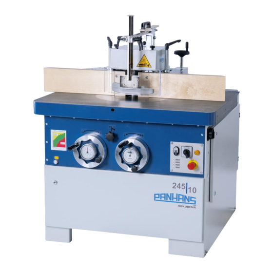
PANHANS 245|10
245|10
Machine-Type:
HOKUBEMA Maschinenbau GmbH
Graf-Stauffenberg-Kaserne, Binger Str. 28 | Halle 120
DE 72488 Sigmaringen | Tel. +49 07571 755-0
E-Mail:
info@hokubema-panhans.de
| Web:
https://hokubema-panhans.de
Advertisement
Table of Contents
Troubleshooting

Subscribe to Our Youtube Channel
Related Manuals for PANHANS 245|10


Summary of Contents for PANHANS 245|10
- Page 1 TRANSLATION OF THE ORIGINAL VERSION Operating Manual Tilting Spindle Moulder / Table Milling Machine PANHANS 245|10 245|10 Machine-Type: HOKUBEMA Maschinenbau GmbH Graf-Stauffenberg-Kaserne, Binger Str. 28 | Halle 120 DE 72488 Sigmaringen | Tel. +49 07571 755-0 E-Mail: info@hokubema-panhans.de | Web:...
-
Page 2: Table Of Contents
General Symbols ..............................7 Symbols in Safety Instructions ..........................8 General ................................9 Intended Use................................. 10 Target Group and Previous Experience......................... 10 Requirements for the Operators .......................... 10 Accident Prevention .............................. 11 General Safety Regulations ........................... 11 Included Components ............................12 Optional Accessories ............................. - Page 3 Electrical Connection ............................ 29 Back-up Fuses (on-site) ............................29 Machine Socket..............................29 Components and Control Elements ......................30 Commissioning ............................. 31 10.1 Switching ON and OFF ............................31 10.2 Rotational Direction Switch ..........................31 10.3 Switching the Spindle ON and OFF........................31 10.4...
- Page 4 Adaptation to the Machine Table (only required for retrofitting) ..................47 16.8.4 Supplementary Protective Cover 1641 (Option) ......................47 16.9 Kickback Guard Type 1648 ............................ 47 16.10 Power Feeders ..............................48 16.10.1 Rigid Console for Power Feeders ............................. 48 Troubleshooting ............................49 Maintenance and Inspection ........................
- Page 5 Figure 7: Lashing points (4 x) ..........................27 Figure 8: Suction nozzles ............................28 Figure 9: Terminal Box............................29 Figure 10: Machine Socket ............................ 29 Figure 11: Components and Control Elements ..................... 30 Figure 12: Main switch ............................31 Figure 13: Control panel ............................31 Figure 14: Unlock service door ..........................
- Page 6 Figure 34: Protection and pressure device 1624 CENTREX ................... 42 Figure 35: Integral fence plates (option) ....................... 43 Figure 36: Integral fence plates - operation and functions ................... 43 Figure 37: Optional Table Slide ..........................43 Figure 38: Safety ruler set ............................. 44 Figure 39: Turntable with opening for clamping ....................
-
Page 7: Introduction
Introduction This operating manual applies to the PANHANS 245|10 tilting spindle moulder. The purpose of this document is to acquaint the user with the machine and enable him to use it to the full extent of its intended capabilities. Additionally it contains important information to operate the machine safely, properly and economically. Ob- servance of the manual helps to avoid hazards, reduce repair costs and downtimes and increase the reliability and service life of the machine. -
Page 8: Symbols In Safety Instructions
Symbols in Safety Instructions Symbol Safety Instruction General danger symbol, which requires the highest attention! Failure to observe may result in damage to the equipment, serious injury or even death. Warning of possible danger from forklift traffic! Non-observance may result in life-threatening injuries. Warning indicates a possible hazard under suspended loads! Non-observance may result in life-threatening injuries. -
Page 9: General
General The PANHANS type 245|10 is a universal tilting spindle moulder with height and tilt adjustable milling arbor, two directions of rotation, quick tool change device, adjustable speed as well as separately adjustable total and partial fence. • The milling spindle is driven by a three-phase motor. -
Page 10: Intended Use
Intended Use The PANHANS 245|10 tilting spindle moulder is used exclusively for machining materials for which the milling cutter used is suitable (e.g. wood, chipboard, veneer). The machines are not suitable for milling metal resp. plas- tic and waste wood which could contain nails, screws and other metal parts. The machine may only be operated on a firm, level surface with a minimum load-bearing capacity of 1,000 kg/m. -
Page 11: Accident Prevention
Accident Prevention To avoid accidents, the following rules must be observed for operation: • Prevent unauthorized persons from gaining access to the machine. • Keep unauthorized persons away from the danger areas. • Repeatedly inform present other persons about existing residual risks (refer to section 4.2.3). •... -
Page 12: Included Components
Hydraulic swivel-away device for milling fence • Tenoning and slotting device type “1376” and matching protective cover “1641” • Integral fence plates for fence type 216 • Patented PANHANS table slide • Kickback guard type “1648” • Central lubrication • Safety rulers •... -
Page 13: Safety
Application Area and Intended Use • Th PANHANS tilting spindle moulder 245|10 is used exclusively for milling of solid wood (soft and hard woods) as well as plastics and wood-containing board materials. • This machine is not suitable for processing metal resp. plastic and scrap wood - which could contain nails, screws and other metal parts. -
Page 14: Permissible Tool Dimensions
4.2.2 Permissible Tool Dimensions Spindle Ø Maximum clamping length Milling cutters Tenoning and slotting tools 30 mm 140 mm 80 - 250 mm max. 300 mm 40 mm 160 mm 80 - 250 mm max. 350 mm 50 mm 160 mm 80 - 250 mm max. -
Page 15: Observe The Environmental Protection Regulations
Electrical equipment must be maintained and cleaned regularly. Pay attention to the danger of crushing on workpiece guides and moving machine parts. Make sure that no unauthorised persons are in the area of the machine. Be aware of the risk of injury from flying tool parts in the event of tool breakage. Therefore wear protective goggles. -
Page 16: Personnel Selection And Qualification - Basic Duties
Spare parts must meet the technical requirements specified by the manufacturer. The exclusive use of original spare parts ensures this. Therefore, only use original spare parts from the manufacturer. Observe the fire alarm and firefighting possibilities. Make the location and operation of fire extinguishers (fire class ABC) known. -
Page 17: Normal Operation
4.3.2 Normal Operation Guards: Take measures to ensure that the machine can only be operated in a safe and functional condition. Only operate the machine when all guards and safety-related devices such as - detachable guards (e.g. tool covers and fence covers), - emergency stop system, sound insulation, suction device etc. -
Page 18: Special Work Within The Scope Of Maintenance Work As Well As Troubleshooting In The Workflow
4.3.3 Special work within the Scope of Maintenance Work as well as Troubleshooting in the Workflow Observe maintenance and inspection activities prescribed in the operating manual! These activities, as well as all other repair work, may only be carried out by qualified personnel! For all work concerning operation, production adjustment, conversion or setting of the machine and its safety-related equipment as well as maintenance and repair, observe switch-on and switch-off procedures according to the operating manual and instructions for maintenance work! -
Page 19: Tool Handling
4.4.4 Tool Handling Tools must be handled with care and tool transport equipment must be used whenever possible. 4.4.5 Tool Clamping Use suitable devices, e.g. setting gauges, to clamp the tool when the machine is at a standstill. To keep the gap between the spindle and the table as small as possible, the matching table insert rings must be used or the optional table slide plate (see ... - Page 20 4.4.9.1 Milling at the fence, where the machining extends over the full workpiece length With workpieces that usually have a right-angled cross-section over their entire length, this machining operation is carried out by using a milling fence. Since the fence rulers are at a 90° angle to the table top, the workpiece can be guided at right angles along the fence rulers.
-
Page 21: Use Of Work Devices With Protective Function
• For accident-free insertion milling of long and short parts (infinitely adjustable from 0 to 1500 mm). 4.4.13.4 Power Feeders • For a safe workpiece feed (refer to section 16.10). You can find further accessories in chapter 20 and in our online shop ... -
Page 22: Hazardous Areas
Hazardous Areas Hazard Area/Action Risk Avoidance Cutting Hazard At the tool • When changing • Wear gloves when changing Mild to severe inju- ries to hands and the cutter head the cutter. • In case of contact with • Keep hands out of the danger fingers the rotating cutter zone. -
Page 23: Machine Data
Milling Fence Type: standard: 215 | option: 216 (fence details see chapter 14) Ring Fence Type: 1639 Tapoa (details see section 14.6) Drive Motor: 5.5 kW (7.5 HP) | option 7.5 kW (10 HP) Motor Voltage: 400 VAC / 50 Hz... -
Page 24: Working Area
Working Area The working area designates the position from which the machine is operated. Working area Figure 2: Working area Emission Levels 5.3.1 Noise Information The values given are emission levels and therefore do not necessarily represent safe workstation values at the same time. -
Page 25: Dimensions
Dimensions Front View 1000 Figure 3: Dimensions - Front view Top View 1 Figure 4: Dimensions - Top view 1 Top View 2 4 drillings for the power feeder acc. to the plate Figure 5: Dimensions - Top view 2 BA_PH_245-10_EN_13-22.docx... -
Page 26: Installation And Connection
and Connection 7 Installation Check Delivery Conditions Check the consignment for completeness and possible transport damage. In case of transport damage, please keep the packaging and inform the shipping company and the manufacturer immediately! Later complaints can- not be accepted. Transport to the Installation Site The machine is delivered on a transport pallet and is bolted to the bottom of the pallet. -
Page 27: Temporary Storage
Fire hazard! Do not smoke and do not light an open fire. Do not use nitro thinner for cleaning. Painted surfaces of the machine can be damaged. Dispose of the packaging material in an environmentally friendly way! Temporary Storage If the machine is not put into operation immediately after delivery, it must be stored carefully in a protected place. -
Page 28: Connecting The Extraction Unit
Depending on the equipment or with older models, these may differ. The valid terminals for your ma- 245|10 63 + 64 on contactor Q3 chine can be found in the circuit diagram (see control cabinet). -
Page 29: Electrical Connection
Machine Socket The machine socket integrated in the machine is located on the right side above the terminal box. It is internally fused with a back-up fuse of 6 - 10 A. Please note: The machine socket only supplies power when the full engine speed has been reached. -
Page 30: Components And Control Elements
Components and Control Elements Figure 11: Components and Control Elements Pos. Description Pos. Description Main switch Manual adjustment for total fence Milling spindle Table top Control panel Table insert rings (table slide plate optionally) Emergency stop Tilt adjustment handwheel with dial gauge Milling fence type 215 Height adjustment handwheel with dial gauge Milling splinter tab (2 x) -
Page 31: Commissioning
Do not start working until the machine has reached full speed (after approx. 10 s). • Switching OFF: Press “” on the switch (F) → The milling cutter is switched off and brought to standstill (braking time < 10 s). BA_PH_245-10_EN_13-22.docx... -
Page 32: Emergency Stop Function
Before restarting the machine, the emergency stop button must be unlocked again. The braking time of the motor to a standstill can be up to 10 seconds. 10.5 Service Door with Safety Switch The front service door of the machine is opened for various maintenance activities (for example, to adjust the speed, tighten or replace the drive belt or lubricate the machine). -
Page 33: Speed Setting
Speed Setting With the 245|10 tilting spindle moulder, the speed is adjusted by shifting the V-belt. Switch off the machine during speed adjustment and secure it against unexpected restarting. Lock the main switch with a padlock! After switching off and locking the main switch, open the front service door and proceed as follows: •... -
Page 34: Tool Change
Tool Change 12.1 With Quick Clamping Device (Standard) The tools used on the machine must comply with EN 847-1! Wear cut-resistant protective gloves when changing tools! • With the spindle running, first press “” on the switch (F) to switch of the spindle (see Figure 13). Then wait approx. -
Page 35: Position The Milling Spindle
Position the Milling Spindle The positioning of the cutter height and spindle tilt is done via the two handwheels at the front, each equipped with an analogue dial gauge. • Left Handwheel → Tilt adjustment in degrees Graduation: 1.0° • Right Handwheel →... -
Page 36: Milling Fences
Milling Fences 14.1 Placing and Aligning the Milling Fence In order to place the fence on the table top and to align it parallel without the need for further tools, all fence types are equipped with a dovetail receptacle (S) on the underside and two spring-mounted centring pins (Z). -
Page 37: Functions And Adjustment Of The Milling Fences
14.2 Functions and Adjustment of the Milling Fences Two different fence types are available for the 245|10 tilting spindle moulder: • Fence Type 215 (standard) → Total fence is manually adjustable via handwheel and partial fence via adjusting screw. → A separate measuring device is required to position the total fence (e.g. setting gauge). -
Page 38: Fence Type 216 (Option)
14.2.2 Fence Type 216 (Option) With the optional fence type 216, the total and partial fence are manually ad- justable. For adjustment, the clamping levers (3) and (6) are released and the fence is adjusted via the hand wheel (2). Afterwards the two clamping levers (3) and (6) must be re-tightened. -
Page 39: Tool Covers For High Milling Arbors
14.3.4 Tool covers for high milling arbors By opening the knurled screws (10), the two cover plates can be moved, which is particularly advantageous with high milling arbours. The opening should always be closed as far as possible without touching the milling arbor or the cutter. -
Page 40: Handwheel Adjustment For Type 216 (Option)
1. Insert the new battery (+ must point downwards!) 2. Push the battery compartment (1) back in completely and check the function of the unit. Further documents: The original operating instructions for the “DE10” unit can be found via the following link: https://www.siko-global.com/adbimage/2642/asset_original/installation-instructions-de10.pdf... -
Page 41: Ring Fence Tapoa 1639
• The height of the workpiece hold-down and the contact guard (2) are adjusted to the required level with the two clamping levers (10) on the rear side of the fence. • The feed strip (3) can be swivelled away by loosening the clamping lever (4) if necessary. Further, it can also be mounted on the other side (with a different spindle rotation direction). -
Page 42: Protection And Pressure Devices
Protection and Pressure Devices If no power feeder is used for milling, a protection and pressure device must be used. 15.1 TYPE 1629 GAMMA V (Standard) The standard protection and pressure device type 1629 GAMMA V is suitable for all milling fences described in section ... -
Page 43: Optional Components
Optional Components 16.1 Integral Fence System for Fence Type 216 The optional milling fence 216 can additionally be equipped with optional integral fence plates. These can be mounted without tools and in just a few steps instead of the standard cast fence plates. -
Page 44: Safety Rulers For The Milling Fence
16.3 Safety Rulers for the Milling Fence The optional safety rulers serve as a continuous guide between the two fence plates. The set consists of: • 2 safety rulers 260 x 6 mm • 3 safety rulers 260 x 3 mm, •... -
Page 45: Tm 100 - Rfid Based Machine Access Control System
16.7 TM 100 - RFID based Machine Access Control System The TM 100 key system offers the highest level of security. With the user data bank, only au- thorised personnel can start the machine by using a personalised RFID key. Included is the TM 100 system with master key (red) for administrator access and four user keys (blue) for authorised persons who are al-... -
Page 46: Tenoning And Slotting Device Type 1376
30° to 150°. The smooth-running, ball-bearing sliding carriage has a sliding length of 710 mm (sliding panel length = 295 mm, slide panel width = 255 mm). Increased risk of accidents due to the high weight of the device! Lifting and placing should be done by two persons or with a suitable hoist (e.g. -
Page 47: Adaptation To The Machine Table (Only Required For Retrofitting)
We recommend drilling the holes according to the sketch above, whereby the dimension 275 mm depends on the cutter head diameter used. • For this purpose, two M12 threads must be fitted (bore diameter = 10.2 mm). • Fasten the tenoning device with M12 x 30 hexagon screws and washers. -
Page 48: Power Feeders
Operating manual of the cor- responding manufacturer. The article numbers can be found in the section 20.6. 16.10.1 Rigid Console for Power Feeders Rigid add-on console for a power feeder. The plat- form (approx. 195 x 180 mm) is mounted on the left side of the table top. -
Page 49: Troubleshooting
→ Close door & lock the safety switch Service door is open → Lock the door safety switch Safety switch of the (see section 10.5) service door is unlocked → Readjust brake (see 18.4) Spindle comes Brake pads worn →... -
Page 50: Maintenance And Inspection
The air velocity to the extraction system must be checked before the initial commissioning and after signifi- cant modification. • If the motor no longer brakes within 10 seconds when switching off, it is essential to contact the customer service. •... -
Page 51: Maintenance Plan
18.3 Maintenance Plan Activity Cleaning the machine Check that the extraction system is fully functional before starting work. Inspect electrical equipment and components for externally visible damage and have this repaired by a qualified electrician if necessary. Check drive belt condition. Check drive belt tension. -
Page 52: Readjust The Motor Brake
• Then switch off the machine and check the braking time to standstill. • If the braking time is still over 10 seconds, repeat the adjustment procedure (see section 18.4) and check the adjustment again. • If the adjustment was not successful, please contact the customer service of the manufacturer. -
Page 53: Change And Tighten The Drive Belt
18.5 Change and Tighten the Drive Belt Switch off the machine during belt replacement and tightening and secure it against unintentional restarting! Lock the main switch with a padlock! The drive belt should be replaced in the event of excessive wear, frayed flanks, traces of oil, porosity or if cross- sectional fractures are present. -
Page 54: Lubrication Instruction
The machine has been extensively test-run at the factory and is lubricated ready for operation. Relubrication before commissioning is therefore not necessary. For subsequent lubrication, use only special grease, e.g.: • PANHANS ZET-GE-MSO • ARCANOL BN 102 • CALYPSOL H 442 B •... -
Page 55: Lubrication Plan
19.2 Lubrication Plan Figure 54: Lubrication points on the machine Figure 55: Central lubrication To keep the machine parts always clean and in perfect condition, excess and/or old grease must be wiped off at the outlet points of all existing grease nipples and other guiding elements! Standard Version Pos. -
Page 56: Options And Accessories
20.1 Technical Extensions Article Description Art. No. MOTOR Motor 7.5 kW (10 HP) instead of 5.5 kW. 4271 20.2 Table Systems Article Description Art. No. TURNTABLE This allows the milling fence types 215 and 216 to be rotated 360°... -
Page 57: Milling Fences
20.3 Milling Fences Article Description Art. No. MILLING FENCE 216 Instead of standard milling fence type 215. Made of die-cast alumin- ium with plane-milled cast iron fence plates with aluminium splinter tabs, length 500 mm; to accommodate optional safety rulers and 4274 mouldboard. -
Page 58: Milling Spindles And Arbors
TENONING AND with eccentric clamp and adjustable mitre fence. SLOTTING DEVICE 1376 4547 Sliding length = 710 mm, height above table approx. 56 mm. Protection cover for the tenoning and slotting device 1376, suitable for PROTECTION COVER 1641 2235 tool diameters from 250 to 350 mm, with suction nozzle Ø 120 mm. -
Page 59: Special Accessories
1 key tag (red) for administrator access CONTROL TM 100 4655 and four user keys (blue) for authorised persons who are allowed to work on the machine. Blue, for user database TM 100 (content 10 pieces). PERSONALISED 4670 USER KEY MASTER KEY Red, for user database TM 100 (content 1 piece). -
Page 60: Disassembly And Scrapping
Disassembly and Scrapping When dismantling and scrapping the machine, the current EU regulations or the respective regulations and laws of the country of operation, which are prescribed for proper dismantling and disposal, must be observed. The aim is to dismantle the machine and its various materials and components properly, to recycle all possible parts and to dispose of non-recyclable components in the most environmentally friendly way. -
Page 61: Eu - Declaration Of Conformity
DE 72488 Sigmaringen (Germany) Fax: +49 (0) 7571 / 755 - 222 hereby declares that the manufactured machine Tilting Spindle Moulder TYPE 245|10 Machine-No.: ......Year of manufacture: ..... in the version provided complies with the following directives: - Machinery Directive 2006/42/EG...
Need help?
Do you have a question about the 245|10 and is the answer not in the manual?
Questions and answers