Sign In
Upload
Manuals
Brands
OXTS Manuals
Receiver
RT3000 T v4
OXTS RT3000 T v4 Manuals
Manuals and User Guides for OXTS RT3000 T v4. We have
2
OXTS RT3000 T v4 manuals available for free PDF download: User Manual
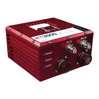
OXTS RT3000 T v4 User Manual (105 pages)
Brand:
OXTS
| Category:
Test Equipment
| Size: 5 MB
Table of Contents
Legal Notices
2
Copyright Notice
2
Revision
2
Contact Details
2
Warranty
3
Product Limitations
3
Limitations of Liability
3
Table of Contents
4
Introduction
10
Easy Operation
11
Self-Correcting
11
Advanced Processing
11
Related Documentation
11
Software Documentation
12
Data Formats Documentation
12
Table 1: Software Manuals
12
Table 2: Data Format Manuals
12
Utilities Documentation
13
Scope of Delivery
13
Table 3: Utilities Manuals
13
Table 4: Summary of RT3000 V4 Standard Kit Components
13
Conformance Notices
14
Regulator Testing Standards
14
Hardware Description
15
Overview
15
RT3000 V4
15
RT3000 T V4
15
Gnss
15
Satellite Constellations
15
Satellite-Based Differential Corrections
15
Dual Antenna
16
Position and Heading Relock
16
Specifications
17
IMU Specification
17
Performance Specification
17
Table 5: RT3000 V4 Inertial Sensor Specifications
17
Notes on Performance Specification
18
Table 6: RT3000 V4 Performance Specifications
18
Notes on Heading Specification
19
Physical Specification
19
Table 7: RT3000 V4 Physical Specifications
19
Export Control Classification
20
Software Installation
21
Table 8: Navsuite Components
21
Figure 1: Windows Firewall Warning Message
22
Hardware Installation
23
Mounting
23
Figure 2: RT3000 V4 Mounting Points (MM)
23
Orientation and Alignment
24
Antennas
24
Antenna Placement and Orientation
24
Dual Antenna Systems
25
Figure 3: Dual Antenna Orientations
25
Multipath Effects on Dual Antenna Systems
26
Operation
26
Front Panel Layout
26
LED Definitions
27
Figure 4: RT3000 V4 Front Panel Layout
27
Table 9: RT3000 V4 Front Panel Descriptions
27
Table 10: Power LED States
27
I/O Connectors
28
Figure 5: RT3000 V4 I/O Connector Pin Layout
28
Table 11: Status LED States
28
Table 12: GNSS LED States
28
Table 13: Main Connector Pin Description
29
Table 14: Auxiliary Connector Pin Description
30
User Cables
31
Figure 6: RT3000 V4 Main User Cable
31
Table 15: RT3000 V4 Main User Cable Pin Description
32
Figure 7: RT3000 V4 Auxiliary User Cable
33
Digital Inputs and Outputs
34
Table 16: RT3000 V4 Auxiliary User Cable Pin Description
34
Table 17: Digital I/O Signals
34
1PPS Output
35
Trigger 1 and 2
35
Figure 8: 1PPS Waveform
35
Wheel Speed Input
36
IMU Sync Output Pulse
36
Co-Ordinate Frame Conventions
36
IMU Frame
36
Oxts NED Navigation Frame
37
Figure 9: RT3000 V4 IMU Coordinate Frame Axes
37
Figure 10: IMU Measurement Origin
37
ISO 8855 ENU Earth-Fixed System
38
Figure 11: Oxts NED Navigation Frame Definition
38
Table 18: Oxts NED Navigation Frame Definition
38
Table 19: ISO 8855 ENU Earth-Fixed System
38
Oxts Horizontal Frame
39
Figure 12: ISO 8855 ENU Earth-Fixed System
39
Figure 13: Oxts Horizontal Frame Definition
39
Table 20: Oxts Horizontal Frame Definition
39
ISO 8855 Intermediate System
40
Oxts Vehicle Frame
40
Figure 14: ISO 8855 Intermediate System
40
Table 21: ISO 8855 Intermediate System
40
ISO 8855 Vehicle System
41
Figure 15: Vehicle Frame Definition
41
Table 22: Vehicle Frame Definition
41
Ethernet Configuration
42
Figure 16: ISO 8855 Vehicle System
42
Table 23: ISO 8855 Vehicle System
42
Connection Details for Ethernet Configuration
43
Figure 17: Configuring the Computer's IP Address for Ethernet Data Transmission
43
Figure 18: In-Line RJ-45 Coupler
44
Table 24: In-Line Coupler Connections
44
Configuring the RT3000 V4
45
Navconfig - Overview
45
Navconfig - Home
45
Navconfig - Start Configuration
46
Figure 19: Navconfig Home Section
46
Navconfig - Read Configuration
47
Figure 20: Navconfig Start/Read Configuration Section
47
Navconfig - Hardware Setup
48
IMU Orientation
48
Figure 21: Navconfig Read Configuration Section
48
Primary Antenna Lever Arm
49
Figure 22: Navconfig IMU Orientation Tab in the Hardware Setup Section
49
Secondary Antenna Lever Arm
50
Figure 23: Navconfig Primary Antenna Tab
50
Lateral and Vertical No-Slip Constraints
51
Figure 24: Navconfig Secondary Antenna Tab in the Hardware Setup Section
51
Figure 25: Navconfig Lateral No-Slip Tab in the Hardware Setup Section
52
Figure 26: Measurement Point for Lateral N-Slip
52
GNSS Differential Corrections
53
Figure 27: Navconfig Vertical No-Slip Tab in the Hardware Setup Section
53
Table 25: GNSS Differential Correction Formats
53
Local Base Station
54
Figure 28: Navconfig Differential Corrections Tab in the Hardware Setup Section
54
Table 26: GNSS Differential Correction Datums
54
Internal NTRIP
55
Figure 29: NTRIP Internal Client
55
External NTRIP
56
Network DGPS
56
Forwarding Corrections
56
Sbas
56
Terrastar (RT3000 T V4 Only)
56
Navconfig - Interfaces
56
Ethernet
56
Ucom
57
Figure 30: UCOM Configuration
57
CAN Output
58
Figure 31: Navconfig CAN Output Configuration Tab
58
CAN Acquisition
60
Figure 32: CAN-FD Output Configuration
60
Serial 1 Output
61
Figure 33: CAN-Acquisition Tab
61
Analogue
62
Table 27: Serial Outputs
62
PPS / Triggers
63
Ptp
63
Navconfig - Environment
63
Initialisation
63
Vehicle Starts
64
GNSS Environment
64
Vibration Levels
64
Heading Lock
64
Garage Mode
65
Surface Tilt
65
Figure 34: Navconfig Surface Tilt Properties in the Environment Section Within Navconfig
65
Table 28: Navconfig Heading Lock Options
65
Enable Local Coordinates
66
Navconfig - Advanced Tools
66
Displace Output
66
Acceleration Filters
66
Figure 35: Navconfig Enable Local Co-Ordinates in the Environment Section
66
Wheel Speed Input
67
Figure 36: Navconfig Acceleration Filters Tab in the Advanced Tools Section
67
Figure 37: Navconfig Wheel Speed Input Tab in the Advanced Tools Section
68
CAN Wheel Speed
69
Output Smoothing
70
Figure 38: CAN Wheel Speed Configuration
70
Slip Points
71
Figure 39: Navconfig Output Smoothing Properties Window
71
GNSS Control
72
Figure 40: Navconfig Slip Points Tab
72
Figure 41: Navconfig GNSS Control Tab in Advanced Tools Within Navconfig
73
GNSS Recovery
74
Global Coordinate System
74
Table 29: GNSS Update Rates
74
Accuracies
75
Figure 42: Navconfig Global Coordinate System Properties Window
75
Commands
76
Time Source
76
Navconfig - Write Configuration
77
Navconfig - Improve Configuration
78
Figure 43: Navconfig Home Section
78
Figure 44: Navconfig Read Configuration
79
Figure 45: Navconfig Improve Configuration Data Source
80
Figure 46: Navconfig Improve Configuration Select Settings
81
Setting up the Base Station
82
Figure 47: Navconfig Improve Configuration Write Configuration
82
Using the RT-Base S
83
Initialisation Process
84
Real-Time Outputs
84
Warm-Up Period
84
Table 30: Quantities Required for Initialisation
84
Post-Processing Data
86
Data Retrieval
86
Post-Processing
87
Table 31: List of Supported FTP Commands
87
Laboratory Testing
89
Accelerometer Test Procedure
89
Gyro Test Procedure
89
Testing the Internal GNSS and Other Circuitry
90
Table 32: Status Field Checks
90
Appendix A - Ensuring Optimal Operation
92
Appendix A - Ensuring Optimal
92
Table 33: Optimal Operation Checks
93
Appendix B - Using the Orientation Measurements
94
Appendix C - Drawing List
95
Table 34: List of Available Drawings
95
Revision History
100
Blank for User Notes
100
Table 35: Revision History
100
Advertisement
OXTS RT3000 T v4 User Manual (107 pages)
Brand:
OXTS
| Category:
Receiver
| Size: 6 MB
Table of Contents
Legal Notices
2
Copyright Notice
2
Revision
2
Contact Details
2
Warranty
3
Product Limitations
3
Limitations of Liability
3
Table of Contents
4
Introduction
11
Easy Operation
12
Self-Correcting
12
Advanced Processing
12
Related Documents
12
Table 1: Supplementary Manuals
12
Scope of Delivery
13
Table 2: Summary of RT3000 V4 Standard Kit Components
13
Conformance Notices
14
Regulator Testing Standards
14
Hardware Description
16
Overview
16
RT3000 V4
16
RT3000 T V4
16
Dual Antenna
16
Quad Constellation
17
Satellite Differential Corrections
17
Specifications
18
Table 3. RT3000 V4 Performance Specifications
18
Table 4: RT3000 V4 Inertial Sensor Specifications
19
Table 5: RT3000 V4 Physical Specifications
19
Heading Accuracy
20
Notes on Specifications
20
Environmental Protection
21
Export Control Classification
21
Table 6. Navsuite Components
22
Software Installation
22
Figure 1: Windows Firewall Warning Message
23
Hardware Installation
24
Mounting
24
Figure 2: RT3000 V4 Mounting Points (MM)
24
Orientation and Alignment
25
Antennas
25
Antenna Placement and Orientation
25
Figure 3: Dual Antenna Orientations
26
Operation
27
Front Panel Layout
27
LED Definitions
27
Figure 4: RT3000 V4 Front Panel Layout
27
Table 7: RT3000 V4 Front Panel Descriptions
27
I/O Connectors
28
Table 8: Power LED States
28
Table 9: Status LED States
28
Table 10: GNSS LED States
28
Figure 5: RT3000 V4 I/O Connector Pin Layout
29
Table 11: Main Connector Pin Description
30
Table 12: Auxiliary Connector Pin Description
30
User Cables
31
Figure 6: RT3000 V4 Main User Cable
32
Table 13: RT3000 V4 Main User Cable Pin Description
32
Figure 7: RT3000 V4 Auxiliary User Cable
34
Table 14: RT3000 V4 Auxiliary User Cable Pin Description
34
Digital Inputs and Outputs
35
1PPS Output
35
Trigger 1 and 2
35
Figure 8: 1PPS Waveform
35
Table 15: Digital I/O Signals
35
Wheel Speed Input
36
IMU Sync Output Pulse
37
Co-Ordinate Frame Conventions
37
IMU Frame
37
Figure 9: RT3000 V4 IMU Coordinate Frame Axes
37
Oxts NED Navigation Frame
38
Figure 10. IMU Measurement Origin
38
Table 16. Oxts NED Navigation Frame Definition
38
ISO 8855 ENU Earth-Fixed System
39
Figure 11: Oxts NED Navigation Frame Definition
39
Table 17: ISO 8855 ENU Earth-Fixed System
39
Oxts Horizontal Frame
40
Figure 12: ISO 8855 ENU Earth-Fixed System
40
Table 18: Oxts Horizontal Frame Definition
40
ISO 8855 Intermediate System
41
Figure 13: Oxts Horizontal Frame Definition
41
Figure 14: ISO 8855 Intermediate System
41
Table 19: ISO 8855 Intermediate System
41
Oxts Vehicle Frame
42
ISO 8855 Vehicle System
42
Figure 15: Vehicle Frame Definition
42
Table 20: Vehicle Frame Definition
42
Ethernet Configuration
43
Figure 16: ISO 8855 Vehicle System
43
Table 21: ISO 8855 Vehicle System
43
Figure 17: Configuring the Computer's IP Address for Ethernet Data Transmission
44
Connection Details for Ethernet Configuration
45
Dual Antenna Systems
45
Figure 18: In-Line RJ-45 Coupler
45
Table 22: In-Line Coupler Connections
45
Multipath Effects on Dual Antenna Systems
46
Configuring the RT
48
Overview
48
Working through Navconfig
48
Navconfig Home Section in Navconfig
49
Figure 19: Navconfig Home Section
49
Start/Read Configuration Section in Navconfig
50
Read Configuration Section
50
Figure 20: Navconfig Start/Read Configuration Section
50
Hardware Setup Section in Navconfig
51
Figure 21: Navconfig Read Configuration Section
51
Figure 22: an RT Device Mounted on Our RT-Strut
52
IMU Orientation Tab
52
Figure 23: Navconfig IMU Orientation Tab in the Hardware Setup Section
53
Primary Antenna Tab
53
Figure 24: Navconfig Primary Antenna Tab
54
Secondary Antenna Tab
54
Figure 25: Navconfig Secondary Antenna Tab in the Hardware Setup Section
55
Figure 26: Navconfig Lateral No-Slip Tab in the Hardware Setup Section
56
Lateral No-Slip and Vertical No-Slip Tabs
56
Figure 27: Measurement Point for Lateral No-Slip
57
Figure 28: Navconfig Lateral No-Slip Tab in the Hardware Setup Section
58
GNSS Differential Corrections Tab
58
Figure 29: Navconfig Differential Corrections Tab in the Hardware Setup Section
59
Table 23: Navconfig Differential Corrections Formats
59
Figure 30: NTRIP Internal Client
60
Ntrip
60
Networked DGPS (WLAN)
62
Sbas
62
Terrastar Corrections
62
Interfaces Section in Navconfig
63
Ethernet Tab
63
CAN Output Tab
63
Figure 31: Navconfig CAN Output Configuration Tab
64
Figure 32: Navconfig CAN Output Configuration Tab - Navigation
65
CAN Acquisition Tab
67
Figure 33: CAN-FD Output Configuration
67
Serial 1 Output Tab
68
Figure 34: CAN-Acquisition Tab
68
Table 24: Serial Outputs
69
Analogue Tab
70
PPS / Triggers Tab
70
PTP Tab
70
Navconfig Environment Section
70
Initialisation
70
Vehicle Starts
70
GNSS Environment
71
Vibration Levels
71
Heading Lock
71
Table 25: Navconfig Heading Lock Options
71
Garage Mode
72
Surface Tilt
72
Figure 35: Navconfig Surface Tilt Properties in the Environment Section Within Navconfig
72
Enable Local Coordinates
73
Advanced Tools Section
73
Displace Output Tab
73
Acceleration Filters Tab
73
Figure 36: Navconfig Enable Local Co-Ordinates in the Environment Section
73
Wheel Speed Input
74
Figure 37: Navconfig Acceleration Filters Tab in the Advanced Tools Section
74
Figure 38: Navconfig Wheel Speed Input Tab in the Advanced Tools Section
76
Output Smoothing Tab
77
Figure 39: Navconfig Output Smoothing Properties Window
77
Slip Points Tab
78
GNSS Control Tab
79
Figure 40: Navconfig Slip Points Tab
79
Figure 41: Navconfig GNSS Control Tab in Advanced Tools Within Navconfig
80
Table 26: Gx/IX™ Compatibility
80
GNSS Recovery Tab
81
Global Coordinate System Tab
81
Table 27: GNSS Update Rates
81
Figure 42: Navconfig Global Coordinate System Properties Window
82
Accuracies Tab
83
Commands Tab
83
The Write Configuration Section of Navconfig
83
Setting up the Base Station
84
Figure 43: Navconfig Write Configuration Page
84
Using the RT-Base S
85
Initialisation Process
86
Real-Time Outputs
86
Warm-Up Period
86
Table 28: Quantities Required for Initialisation
86
Improving the Configuration after a Warm-Up
87
Committing the Configuration to the RT
87
Figure 44: Navconfig Home Section
87
Read Configuration Section in Navconfig Improved Configuration Wizard
88
Figure 45: Navconfig Read Configuration
88
Post-Processing Data
92
Appendix A - Ensuring Optimal Operation
93
Table 29: Optimal Operation Checks
93
Appendix B - Using the Orientation Measurements
95
Appendix C - Drawing List
96
Table 30: List of Available Drawings
96
Table 31: Revision History
102
Blank for User Notes
103
Blank for User Notes
105
Advertisement
Related Products
OXTS RT3000 v4
OXTS RT3000
OXTS RT3000s
OXTS RT3002
OXTS RT3002G
OXTS RT3003
OXTS RT3003G
OXTS RT3000 16g v4
OXTS RT3100
OXTS RT3102G
OXTS Categories
Measuring Instruments
Car Navigation system
GPS
UPS
Test Equipment
More OXTS Manuals
Login
Sign In
OR
Sign in with Facebook
Sign in with Google
Upload manual
Upload from disk
Upload from URL