Table of Contents
Advertisement
Quick Links
Advertisement
Table of Contents

Related Manuals for OXTS RT3000 v4

Summary of Contents for OXTS RT3000 v4
-
Page 2: Legal Notices
Document Revision: 231211 (See Revision History for detailed information). Contact details Oxford Technical Solutions Limited Park Farm Business Centre Middleton Stoney Oxfordshire OX25 4AL United Kingdom Tel: +44 (0) 1869 814 253 Fax: +44 (0) 1869 251 764 Web: https://www.oxts.com Email: support@oxts.com Oxford Technical Solutions Ltd Page 1 of 110... -
Page 3: Warranty
Limitations of liability The purchaser shall indemnify OxTS from all third-party claims arising from any product use not covered by the parameters of the product datasheet or not approved by OxTS. Oxford Technical Solutions Ltd... -
Page 4: Table Of Contents
Scope of delivery ....................................12 Conformance notices ................................... 13 Regulator testing standards ................................. 13 Hardware description ................................... 15 Overview ........................................ 15 RT3000 v4 ....................................... 15 RT3000 T v4 ....................................15 Dual antenna ....................................... 15 Quad constellation .................................... 16 Satellite differential corrections ..............................16 Specifications ...................................... - Page 5 Wheel speed input ..................................35 IMU sync output pulse ................................36 Co-ordinate frame conventions ..............................36 IMU frame ......................................36 OxTS NED navigation frame ..............................37 ISO 8855 ENU earth-fixed system ............................38 OxTS horizontal frame ................................39 ISO 8855 intermediate system ............................... 40 OxTS vehicle frame ..................................
- Page 6 Networked DGPS (WLAN) ................................61 SBAS ........................................61 TerraStar corrections.................................. 61 Interfaces section in NAVconfig ..............................62 Ethernet tab ....................................62 CAN Output tab ....................................62 CAN Acquisition tab ..................................66 Serial 1 Output tab ..................................67 Analogue tab ....................................69 PPS / Triggers tab ..................................
- Page 7 Real-time outputs ..................................... 85 Warm-up period ....................................85 Improving the configuration after a warm-up ........................86 Committing the configuration to the RT ..........................86 Read configuration section in NAVconfig improved configuration wizard............. 87 Post-processing data ................................... 91 Appendix A – Ensuring optimal operation............................. 92 Appendix B –...
- Page 8 Figure 3: Dual antenna orientations ..............................25 Figure 4: RT3000 v4 front panel layout ............................26 Figure 5: RT3000 v4 I/O connector pin layout ..........................28 Figure 6: RT3000 v4 main user cable ............................. 31 Figure 7: RT3000 v4 auxiliary user cable ............................33 Figure 8: 1PPS waveform ..................................
- Page 9 Figure 46: NAVconfig improve configuration data source ...................... 88 Figure 47: NAVconfig improve configuration select settings....................89 Figure 48: NAVconfig improve configuration write configuration ..................90 Oxford Technical Solutions Ltd Page 8 of 110...
- Page 10 List of tables Table 1: Supplementary manuals..............................11 Table 2: Summary of RT3000 v4 standard kit components ....................12 Table 3. RT3000 v4 performance specifications ........................17 Table 4: RT3000 v4 inertial sensor specifications ........................18 Table 5: RT3000 v4 physical specifications ..........................18 Table 6.
-
Page 11: Introduction
Important information is highlighted throughout this manual in these boxes. The RT family consists of the RT500 v1, RT1003 v2, RT3000 v3 and RT3000 v4. (N.B. The RT3000 v4 has a variant supporting Terrastar™ called the RT3000 T v4. Except when explicitly mentioned, when this manual refers to the RT3000 v4, it refers to both the R3000 v4 and RT3000 T v4). -
Page 12: Easy Operation
This manual covers the installation and operation of RT systems, but it is beyond its scope to provide details on service or repair. Contact OxTS support or your local representative for customer service-related inquiries. Additional manuals provide further information on some of the software and communication types mentioned in this manual. -
Page 13: Scope Of Delivery
The standard kits are supplied complete with user cable, an Ethernet cable and crossover, software, a calibration certificate, a tape measure, and a quick start guide. Table 2 lists all items that are delivered with each standard RT3000 v4 kit. Table 2: Summary of RT3000 v4 standard kit components... -
Page 14: Conformance Notices
Conformance notices The RT3000 v4 complies with all emissions and immunity limits for the standards stated on the Declaration of Conformity. These limits are designed to provide reasonable protection against harmful interference in business, commercial and industrial uses. This equipment generates, uses, and can radiate radio frequency energy and, if not installed and used in accordance with the instructions, may cause harmful interference to radio communications. - Page 15 ICES-003 Issue 6 January 2016 – Information Technology Equipment (Including Digital Apparatus) – Limits and Methods of Measurement. Oxford Technical Solutions Ltd Page 14 of 110...
-
Page 16: Hardware Description
Comes with dual frequency GPS, GLONASS, Galileo and BeiDou enabled as standard. The RT3000 v4 is RTK capable and has dual antennas. 100 Hz, 200 Hz and 250 Hz versions are available. The RT3000 v4 is able to run the OxTS RT-Range Hunter feature codes for ADAS testing. -
Page 17: Quad Constellation
Quad constellation Tracking satellites from GPS, GLONASS, Galileo and BeiDou constellations allows the RT to utilise all the available position satellites. In open sky conditions, this benefit is smaller as GPS signals alone are unlikely to be interrupted and full accuracy can be achieved almost 100% of the time. -
Page 18: Specifications
For single antenna systems, the heading accuracy is only achieved under dynamic conditions. Under benign conditions, such as motorway driving, the performance will degrade. The performance is undefined when stationary for prolonged periods of time. Table 3. RT3000 v4 performance specifications Parameter RT3000 v4... -
Page 19: Table 4: Rt3000 V4 Inertial Sensor Specifications
Using dual antenna with 1 m separation baseline. Higher accuracy can be achieved with wider antenna separation. Table 4: RT3000 v4 inertial sensor specifications Accelerometers RT3000 v4 / RT3000 T v4 Full range ±8 g... -
Page 20: Notes On Specifications
“1” specification is used because the mounting of the RT compared to the vehicle gives an offset the RT cannot measure. The accuracy of the product will depend on the operating mode of the GNSS. For example, an RT3000 v4 operating without differential corrections enabled will have the specifications of the SPS mode only. -
Page 21: Environmental Protection
Non-ideal mounting of the GNSS antennas will reduce the heading accuracy, particularly for dual antenna systems. Environmental protection The RT3000 v4 is rated to IP65. To achieve IP65 it is necessary to have connectors fitted to both TNC antenna connectors and to use self-amalgamating tape over the TNC connectors. Export control classification Export control regulations are subject to change, and so the classification of the RT may also change. -
Page 22: Software Installation
32 bit operating systems. The first time some OxTS applications are run, a firewall warning message similar to that shown in Figure 1 may be triggered. This is because the program is attempting to listen for, and communicate with, OxTS devices on the network. -
Page 23: Figure 1: Windows Firewall Warning Message
Figure 1: Windows Firewall warning message Ensure both Private and Public networks are selected to ensure the software can continue functioning when moving from one type to another. Oxford Technical Solutions Ltd Page 22 of 110... -
Page 24: Hardware Installation
If the vehicle experiences high shocks, then vibration mounts may be required. The RT3000 v4 is compatible with the RT-Strut product from OxTS to provide a quick and secure vehicle mounting solution. -
Page 25: Orientation And Alignment
Antennas The RT3000 v4 has TNC connectors for the primary and secondary GNSS antennas. Antennas used with the RT must at least be capable of tracking the GPS L1 signal for operation and additionally the GPS L2 signal for RTK performance. -
Page 26: Figure 3: Dual Antenna Orientations
Figure 3: Dual antenna orientations The bases of the antennas are parallel, but the cables exit in different directions. The cables exit in the same direction but the bases of the antennas are not parallel. The bases of the antennas are parallel and the cables exit in the same direction. This configuration will achieve the best results. Multipath affects dual antenna systems on stationary vehicles more than moving vehicles and it can lead to heading errors of more than 0.5°... -
Page 27: Operation
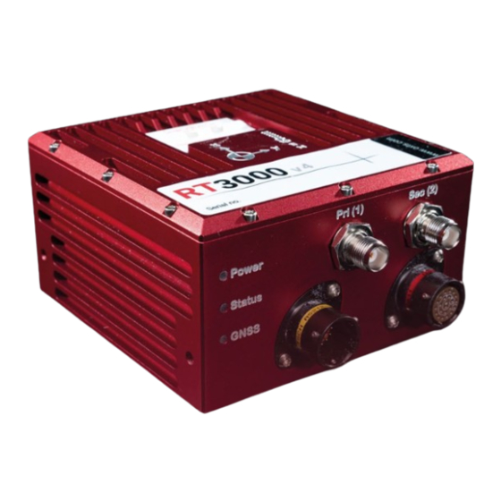
Operation Front panel layout Figure 4 shows the layout of the RT3000 v4 front panel. Table 7 lists the parts of the front panel labelled in Figure 4. Figure 4: RT3000 v4 front panel layout Table 7: RT3000 v4 front panel descriptions... -
Page 28: I/O Connectors
The GNSS receiver has an integer (good) calibrated heading lock. I/O connectors There are two I/O user cable cable connectors on the RT3000 v4 front panel. The main connector is a male 22- pin Deutsch AS612-35PA connector, marked with a yellow ring. The auxiliary connector is a female 22-pin Deutsch AS612-35SN connector, marked with a red ring. -
Page 29: Figure 5: Rt3000 V4 I/O Connector Pin Layout
Figure 5: RT3000 v4 I/O connector pin layout Table 11 and Table 12 show the pin descriptions. Oxford Technical Solutions Ltd Page 28 of 110... -
Page 30: Table 11: Main Connector Pin Description
Table 11: Main connector pin description Pin # Function Description Supply+ Power supply + Supply- Power supply - RS232 Tx Serial nav data transmit RS232 Rx Serial nav data receive Digital 5 Radio data Tx Serial radio data transmit Radio data Rx Serial radio data receive Digital 2 CAN+... -
Page 31: User Cables
Reserved User cables The RT3000 v4 standard kit is supplied with a user cable for quick access to the main interfaces. The J1 connector of the 14C0038 user cable connects to the main I/O connector and connectors J2–J7 provide connections for the inputs and outputs. Figure 6 shows the cable diagram and Table 13 shows the pin descriptions for the interface connectors. -
Page 32: Figure 6: Rt3000 V4 Main User Cable
Figure 6: RT3000 v4 main user cable Table 13: RT3000 v4 main user cable pin description Connector Interface Connector details Function Terminate to Nav data RS232 Rx J1-4 RS232 9-way male D-type Nav data RS232 Tx J1-3 RS232 common J1-12... - Page 33 CAN ground J4-3 CAN+ J1-9 Digital 1 J1-11 Digital 2 J1-8 Digital 3 J1-15 Digital 4 J1-19 Digital I/O 9-way female D-type Digital 5 J1-5 Digital ground J1-18 Digital ground J1-18 Digital ground J1-18 Digital ground J1-18 Ethernet transmit+ J1-20 Ethernet transmit- J1-13 Ethernet...
-
Page 34: Figure 7: Rt3000 V4 Auxiliary User Cable
Figure 7: RT3000 v4 auxiliary user cable Table 14: RT3000 v4 auxiliary user cable pin description Connector Interface Connector details Function Terminate to J1-14 J1-20 J1-13 Supply+ J1-11 Power & 8 pole M12 female Ethernet Supply+ J1-11 J1-12 Supply- J1-10... -
Page 35: Digital Inputs And Outputs
Digital inputs and outputs Table 15 describes each of the signals on the Digital I/O connector J5 of the main user cable. A more detailed explanation of each signal can be found below. Table 15: Digital I/O signals Pin# Function Signal Description Pulsed output from primary GNSS receiver, synchronised with the... -
Page 36: Wheel Speed Input
being generated. The trigger inputs have a pull-up resistor so they can be used with a switch or as a CMOS input. Input signal characteristics: 0 V and 5 V input low < 0.6 V high > 2.6 V In output mode, the trigger generates pulses based on distance or in synchronisation with the IMU clock rate. -
Page 37: Imu Sync Output Pulse
X-axis points forwards, the positive Y-axis points right and the positive Z-axis points down. The RT3000 v4 can be mounted in any orientation, it is not necessary for its axes to match those of the host vehicle. The configuration file will specify the transformation from the IMU frame to the vehicle frame. -
Page 38: Oxts Ned Navigation Frame
Figure 10. IMU measurement origin OxTS NED navigation frame The OxTS navigation frame is attached to the vehicle but does not rotate with it. The down axis is always aligned to the gravity vector and north always points north. Table 16. OxTS NED navigation frame definition... -
Page 39: Iso 8855 Enu Earth-Fixed System
Figure 11: OxTS NED navigation frame definition ISO 8855 ENU earth-fixed system The ISO earth-fixed system is attached to the vehicle but does not rotate with it. The north and east axes are perpendicular to the gravity vector and north always points north. -
Page 40: Oxts Horizontal Frame
The OxTS horizontal frame (sometimes called the level frame) is attached to the vehicle but does not rotate with the roll and pitch of the vehicle. It rotates by the heading of the vehicle. The definition of the OxTS Horizontal frame is listed in Table 18 and shown in Figure 13. -
Page 41: Iso 8855 Intermediate System
Figure 13: OxTS horizontal frame definition The OxTS horizontal frame is attached to the vehicle. The longitudinal and lateral axes remain parallel to a horizontal plane. The longitudinal axis is also parallel to the vehicle’s heading when viewed from above. -
Page 42: Oxts Vehicle Frame
OxTS vehicle frame The OxTS vehicle frame is attached to the body of the vehicle. It is related to the INS through the rotations in the Orientation page of NAVconfig. It can be changed while the INS is running using the Quick Config tool of NAVdisplay. -
Page 43: Ethernet Configuration
Figure 16: ISO 8855 vehicle system Table 21: ISO 8855 vehicle system Axis Description This is the forward direction of the vehicle This is the left direction of the vehicle This is the up direction of the vehicle The ISO vehicle frame is attached to the vehicle and rotates with it in all three axes. The X-axis remains parallel to the vehicle’s heading, while the Y-axis points to the left and is perpendicular to the vehicle’s vertical plane of symmetry. -
Page 44: Figure 17: Configuring The Computer's Ip Address For Ethernet Data Transmission
The IP address of the computer being used to communicate with the RT may need to be changed so it matches the subnet. For example, 195.0.0.200 should be available since this IP address is never used by the RT by default. -
Page 45: Connection Details For Ethernet Configuration
Connection details for Ethernet configuration The RJ-45 connector on the 14C0038x user cable is designed to be connected directly to a network hub. To extend the cable it is necessary to use an in-line coupler. This is two RJ-45 sockets wired together in a straight- through configuration. -
Page 46: Multipath Effects On Dual Antenna Systems
To use the measurements properly the RT needs to know the angle of the GNSS antennas compared to the angle of the RT. This is very difficult to measure accurately without specialised equipment, therefore the RT needs to measure this itself as part of the warm-up process. The RT will lock on to satellites, but it cannot estimate heading so it cannot start. - Page 47 The dual antenna system in the RT works by comparing the carrier-phase measurements at the two antennas. This tells the system the relative distance between the two antennas and which way they are pointing (the heading). For the heading to be accurate the GNSS receivers must measure the relative position to about 3 mm.
-
Page 48: Configuring The Rt
Configuring the RT To obtain the best results from your RT it will be necessary to configure the RT to suit the installation and application before using it. The program NAVconfig can be used to do this. This section describes how to use NAVconfig and gives additional explanations on the meanings of some of the terms used. -
Page 49: Navconfig Home Section In Navconfig
NAVconfig supports English and Chinese (simplified) languages. You can switch language in NAVconfig by clicking on the ‘Settings’ button at the bottom left of the window and choosing your preferred language from the options. If you are connected to a device or editing a configuration file from an RD file then it is possible to view information related to the device in NAVconfig. -
Page 50: Start/Read Configuration Section In Navconfig
Start/Read Configuration section in NAVconfig Figure 20: NAVconfig Start/Read Configuration section This section becomes available when you choose “New configuration” or “Modify configuration” from the Home section. It is important to ensure the correct Product type and version is selected. The settings available in NAVconfig vary depending on the product type and version chosen. -
Page 51: Hardware Setup Section In Navconfig
Figure 21: NAVconfig Read Configuration section Read settings from a folder: It is possible to store a configuration in a folder. The configuration comprises several files, so it is tidier to keep it in a folder by itself. To read the configuration from a folder, select this option and then specify a folder by clicking the ‘Browse…’... -
Page 52: Imu Orientation Tab
IMU orientation tab The IMU orientation tab is used to define the vehicle co-ordinate frame relative to the RT’s co-ordinate frame. It is important to get the orientation correct as although settings entered on this page do not affect the accuracy of the RT, if the outputs are not properly rotated to the vehicle frame then the measurements will appear incorrect. -
Page 53: Primary Antenna Tab
Figure 23: NAVconfig IMU orientation tab in the Hardware Setup section For correct initialisation, it is necessary to get the heading orientation correct. The RT gets its initial heading by assuming the vehicle is travelling forwards in a straight line. If the definition of the vehicle’s x-axis (forward direction) is incorrect in the RT then it will not initialise correctly when the vehicle drives forwards. -
Page 54: Secondary Antenna Tab
Figure 24: NAVconfig Primary Antenna tab It is necessary to tell the RT the distance between its measurement origin (shown in Figure 10) and the GNSS antenna’s measurement point. This should be entered in the vehicle’s co-ordinate frame. The RT will try to improve the position of the primary GNSS antenna during use. To use the values the RT has estimated use the “Improve configuration”... -
Page 55: Figure 25: Navconfig Secondary Antenna Tab In The Hardware Setup Section
If the angle between the antennas cannot be estimated within a 3° tolerance then contact OxTS support for techniques for identifying the angle of the antennas. The ‘Enable static initialisation’ option is useful for slow moving vehicles or where it is essential to start the RT running before moving (for example in autonomous vehicles). -
Page 56: Lateral No-Slip And Vertical No-Slip Tabs
The RT will improve the estimate of the secondary antenna orientation settings. Use the “Improve configuration” option to use the improved values. Lateral No-slip and Vertical No-slip tabs This feature uses characteristics of land vehicle motion to improve heading and slip angle and to reduce drift. Specifying the position of the non-steered wheels makes a huge difference to the lateral drift performance of the RT when GNSS is not available. -
Page 57: Figure 27: Measurement Point For Lateral No-Slip
steering of the rear wheels does not significantly affect the results. Figure 27: Measurement point for Lateral No-slip Measuring from the RT, measure the distances to the non-steered axle position in each axis in the vehicle co- ordinate frame. Select the direction from the dropdown lists and enter the distances. The measurements are made to an accuracy of 10 cm. -
Page 58: Gnss Differential Corrections Tab
Figure 28: NAVconfig Lateral No-slip tab in the hardware Setup section When using No-Slip features, the RT can estimate the slip angle offset of the RT compared to the vehicle. After the RT is initialised and warmed-up, use the Improve configuration option from the NAVconfig Home section to automatically read the RT’s slip angle offset estimate. -
Page 59: Figure 29: Navconfig Differential Corrections Tab In The Hardware Setup Section
Figure 29: NAVconfig Differential corrections tab in the Hardware Setup section Table 23: NAVconfig Differential corrections formats Correction type Description RTCA RTCA is the standard adopted for aircraft. It was the first open standard to use 1 cm corrections. The RT-Base S and GPS-Base products use RTCA RTCM RTCM is the most common open standard used for differential corrections RTCMV3... -
Page 60: Ntrip
When selected, the “Enable NTRIP corrections” checkbox box configures the RT for RTCMv3 corrections and sends an NMEA GGA message out from J3 back to the NTRIP server. The RT3000 v4 includes an internal NTRIP client. Select ‘Use Internal Client’ to configure the settings of the NTRIP client inside the RT. - Page 61 Oxford Technical Solutions Ltd Page 60 of 110...
-
Page 62: Networked Dgps (Wlan)
Wi-Fi when connected to an RT-XLAN. When Network correction transmitter is selected, an RT will broadcast differential corrections it is receiving via a radio modem from an OxTS base station, using its RT-XLAN. Other RT devices that are on the network as the broadcasting RT, will then be able to receive the DGPS messages and use them. -
Page 63: Interfaces Section In Navconfig
Interfaces section in NAVconfig This section contains options for configuring the interfaces of the RT. Some of these settings are feature code controlled so may not be visible to all users on all devices. Ethernet tab The Ethernet settings include configuring the Ethernet data output rate, packet type and Triggers for the RT. You can also enable the Driving Robot interface and input the Driving robot IP if you are using a Driving robot with your RT. -
Page 64: Figure 31: Navconfig Can Output Configuration Tab
Figure 31: NAVconfig CAN output configuration tab You can select individual messages or enable all messages by choosing them from the table displayed. Depending on the baud rate selected, the suggested maximum CAN messages per second will change. A warning message will appear if the combined rate of all current navigation and status messages will overload the CAN bus at the selected baud rate. -
Page 65: Figure 32: Navconfig Can Output Configuration Tab - Navigation
The Navigation tab is where navigation-related CAN messages are configured for output. The table can be sorted in ascending or descending order by clicking any column header. This is particularly useful when checking for enabled/disabled messages. Figure 32: NAVconfig CAN output configuration tab - Navigation Each message can be enabled/disabled by clicking in the appropriate cell and selecting from the dropdown menu. - Page 66 appear in the list more than once. At a data rate of 100 Hz, each message in the Status tab will be transmitted on the CAN bus once per second. The Prefix and Suffix boxes can be used to quickly add alpha-numeric strings to the beginning and end of all message names, while the Identifier offset box allows users to quickly apply an offset to all CAN IDs.
-
Page 67: Can Acquisition Tab
Figure 33: CAN-FD output configuration Choose a Nominal bit rate from the dropdown list. If you want to adjust the Flexible data rate, select the checkbox and then you can choose the Data bit rate from the additional dropdown list and specify the sample points. CAN Acquisition tab The CAN Acquisition tab is where incoming CAN signals are defined. -
Page 68: Serial 1 Output Tab
Select a Packet type and Baud rate. By default, data on the serial port is output using 8-N-1, although odd/even parity and two stop bits are available by using Advanced commands. Please contact support@oxts.com details on this. If the NMEA packet type is selected, the NMEA tab will appear in the properties window. In this tab the NMEA messages to output on the serial port are selected by choosing the data rate for each message type from the dropdown lists and clicking the checkbox for when to generate the message. -
Page 69: Table 24: Serial Outputs
NMEA sentences A special set of messages output in GREIS format to be used with Javad Javad I+RTK receivers. For assistance please contact OxTS for support Used for marine applications. Identical to NCOM output but with the addition of MCOM... -
Page 70: Analogue Tab
Analogue tab The Analogue option is used for configuring the RT-ANA companion product. There are 16 channels in the RT- ANA, numbered from 0 to 15. The Measurement, Range, and Min and Max values for all 16 channels can be configured. -
Page 71: Gnss Environment
GNSS environment Select a predefined value from the dropdown list. If the system is used predominantly in open-sky, then the Open skies setting should be used. In environments with a lot of GNSS multipath then Some obstructions or Frequent obstructions can be used depending on the environment. -
Page 72: Garage Mode
This option can cause problems during the warm-up period if the vehicle remains stationary for a long time and then drives suddenly Note: The heading of most vehicles does change if the steering wheel is turned while the vehicle is stationary. Junctions and pulling out of parking spaces are common places where drivers turn the steering wheel while not moving. -
Page 73: Enable Local Coordinates
CAN bus. On the NCOM output the non-filtered values are output together with the filter characteristics and the NCOM decoders provided by OxTS will implement the chosen filter. The linear acceleration and the angular acceleration can be configured separately. -
Page 74: Wheel Speed Input
Due to vibration the accelerations (both linear and angular) are noisy. In particular, angular acceleration is normally filtered when it is used. The RT can filter the acceleration outputs using a second order low-pass filter. The characteristics of the filter can be set and viewed in the Acceleration Filters tab in the Advanced Tools section of NAVconfig. - Page 75 As with the Lateral No-slip feature, the wheel speed input can only be used on land vehicles; aircraft and marine vehicles cannot use this option. The wheel speed must not be used on a steered wheel, it must be used on a wheel that is measuring the forward direction of the vehicle.
-
Page 76: Figure 38: Navconfig Wheel Speed Input Tab In The Advanced Tools Section
Figure 38: NAVconfig wheel speed Input tab in the advanced tools section The distances from the measurement point on the RT to the measurement point of the wheel speed encoder in the vehicle coordinate frame should be input. The directions can be selected from the dropdown lists. If the wheel speed is from a prop shaft then the distance should be measured half way between the two wheels. -
Page 77: Output Smoothing Tab
The wheel speed corrections will not be as effective in reducing the drift of the RT if the wheel speed is measuring two wheels (i.e. after a differential), since the actual position of the wheel is required for accurate navigation. If a post-differential encoder must be used then the accuracy cannot be guaranteed. For best results, a front wheel drive vehicle should be used with the wheel speed on a rear wheel. -
Page 78: Slip Points Tab
If a large error is accumulated (for example, if GNSS is not available for a long period of time) then it may take a very long time to apply the correction. Under these circumstances it may be preferable to “jump” the measurement to the correct value quickly. -
Page 79: Gnss Control Tab
Figure 40: NAVconfig Slip Points tab GNSS control tab The GNSS control tab contains advanced options that control how the GNSS information is managed in the RT. The GNSS Algorithm tab can be used to select the algorithm used for merging the GNSS and the inertial data in the Kalman filter. -
Page 80: Figure 41: Navconfig Gnss Control Tab In Advanced Tools Within Navconfig
Figure 41: NAVconfig GNSS Control tab in Advanced Tools within NAVconfig The GNSS Control tab gives a choice of two algorithms for computing the GNSS measurements. The default option is to use the algorithm provided by the GNSS receiver. Using this algorithm, the RT will accept position and velocity from the GNSS and use it to update the Kalman filter. -
Page 81: Gnss Recovery Tab
The RT families have different GNSS receivers which have different update rates for position and velocity. Table 27 shows the update rates of the RTs. Table 27: GNSS update rates Product family Position Velocity gx/ix (position) gx/ix (velocity) RT3000 v4 4 Hz 4 Hz 4 Hz 4 Hz RT3000 T v4 4 Hz 10 Hz... -
Page 82: Figure 42: Navconfig Global Coordinate System Properties Window
If Geoid (receiver default) is selected, the altitude will be relative to the geoid used in the GNSS receivers. A Custom geoid file can be used for local variations. To download supported geoid files, go to http://support.oxts.com/local-geoid-files. file must saved... -
Page 83: Accuracies Tab
Using the Commands tab you can enter device-specific commands that apply specific features or perform actions onto the RT. The OxTS technical support team often use these and can provide you with a list of useful commands if you request them at support@oxts.com. -
Page 84: Setting Up The Base Station
Figure 43: NAVconfig Write Configuration page Enter the IP address of the RT you want to configure or select it from the dropdown list. The dropdown box will list all systems currently connected to the computer’s network so ensure to select the correct system if there are multiple listed. -
Page 85: Using The Rt-Base S
The position of the base station GNSS antenna can either be determined by the base station GNSS receiver or can be surveyed in by a chartered surveyor. If the base station GNSS receiver determines its own position, through position averaging, then any error in the base station receiver will also result in error at the RT. In order to relate the RT signals to maps, or other items on the world, it is necessary to have a surveyor measure the position of the GNSS antenna and then tell the base station GNSS receiver what position to use. -
Page 86: Initialisation Process
Initialisation process Before the RT can start to output all the navigation measurements, it needs to initialise itself. In order to initialise, the RT needs all the measurements listed in Table 28. Table 28: Quantities required for initialisation Quantity Description Time Measured by internal GNSS Position... -
Page 87: Improving The Configuration After A Warm-Up
Track the errors in the inertial sensor during their warm-up period (when their errors change more quickly than normal). During this period it is necessary to drive the vehicle or the errors will not be estimated and the specification will not be reached. -
Page 88: Read Configuration Section In Navconfig Improved Configuration Wizard
Read configuration section in NAVconfig improved configuration wizard If you are connected to a device via Wi-Fi or Ethernet, then select “Read settings from a device” and choose the device from the available list. If the file has been logged to the PC already then you can choose ‘Read settings from a data (RD) file’... - Page 89 Figure 46: NAVconfig improve configuration data source The Select Settings screen will appear. From the list displayed, select the settings that you wish to view. These will be determined according to what is enabled on your device. Oxford Technical Solutions Ltd Page 88 of 110...
- Page 90 Figure 47: NAVconfig improve configuration select settings Select the settings that you wish to improve in the configuration from the options available. By clicking the down arrows, you can expand the settings and view the values that have been improved after the warm-up. It is recommended that you review these before clicking ‘Next’...
- Page 91 Figure 48: NAVconfig improve configuration write configuration Before you write the improved settings to the device, choose whether you want to apply the settings immediately or after a power cycle. Oxford Technical Solutions Ltd Page 90 of 110...
-
Page 92: Post-Processing Data
The software suite provided with the RT includes the NAVsolve software which can be used to reprocess the data. The NAVsolve Wizard also gives the user the ability to change the NCOM binary output format to text. A full explanation of NAVsolve is given in the “NAVsolve manual”, which can be downloaded from the OxTS support website. -
Page 93: Appendix A - Ensuring Optimal Operation
In order to maximise performance and ensure optimal operation, there are a number of areas to consider during installation and operation of the RT3000 v4 system. Table 29 lists the topics to pay attention to. Table 29: Optimal operation checks... - Page 94 Able to drive in a straight line and exceed speed threshold for kinematic initialisation Care not to exceed initialisation speed while reversing or turning Device status is monitored Vehicle operation Avoid extended periods in blocked or obstructed GNSS environments without additional aiding sources such as a wheel speed Oxford Technical Solutions Ltd Page 93 of 110...
-
Page 95: Appendix B - Using The Orientation Measurements
Appendix B – Using the orientation measurements This section has been provided to clarify the definitions of heading, pitch and roll that are output by the RT. The RT uses quaternions internally to avoid the problems of singularities and to minimise numerical drift on the attitude integration. -
Page 96: Appendix C - Drawing List
If you require a drawing, or different revision of a drawing, that is not here then contact Oxford Technical Solutions. Table 30: List of available drawings Revision Comments 14A0100 RT3000 v4 system outer dimensions drawing 14C0038 RT3000 v4 primary user cable 14C0213 RT3000 v4 aux user cable 77C0002B... - Page 99 Oxford Technical Solutions Heyford Park Upper Heyford Oxfordshire OX25 www.oxts.com Confidential...
-
Page 102: Table 31: Revision History
Revision history Table 31: Revision history Revision Comments 231211 New Manual Oxford Technical Solutions Ltd Page 101 of 110... -
Page 103: Blank For User Notes
Blank for user notes Oxford Technical Solutions Ltd Page 102 of 110... - Page 104 Oxford Technical Solutions Ltd Page 103 of 110...
-
Page 105: Blank For User Notes
Blank for user notes Oxford Technical Solutions Ltd Page 104 of 110... - Page 106 Oxford Technical Solutions Ltd Page 105 of 110...
- Page 107 Oxford Technical Solutions Park Farm Business Centre Middleton Stoney, OX25 4AL United Kingdom Reg. in England and Wales No. 3534778 Oxford Technical Solutions Ltd Page 106 of 110 © 2023...
Need help?
Do you have a question about the RT3000 v4 and is the answer not in the manual?
Questions and answers