Sign In
Upload
Manuals
Brands
Oshkosh Corporation Manuals
Boom Lifts
JLG M400Anarrow
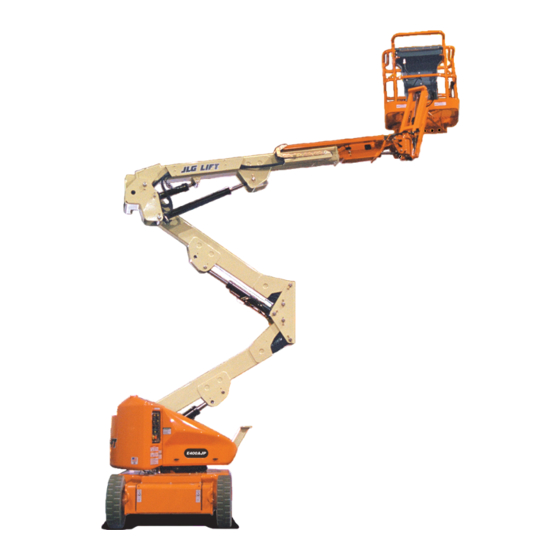
Oshkosh Corporation JLG M400Anarrow Manuals
Manuals and User Guides for Oshkosh Corporation JLG M400Anarrow. We have
1
Oshkosh Corporation JLG M400Anarrow manual available for free PDF download: Service And Maintenance Manual
Oshkosh Corporation JLG M400Anarrow Service And Maintenance Manual (261 pages)
Brand:
Oshkosh Corporation
| Category:
Boom Lifts
| Size: 20 MB
Table of Contents
Bhydraulic System Safety
3
Maintenance
3
Table of Contents
5
Section 1 - Specifications
16
Operating Specifications
16
Capacities
16
Battery Charger
16
Drive System
16
Hydraulic Pump/Electric Motor Assembly
16
Generator
16
Tires
16
Dimensional Data
17
Function Speeds
17
Machine Orientation When Doing Function Tests
18
Torque Specifications
18
Cylinder Specifications
19
Major Component Weights
19
Critical Stability Weights
20
Pressure Settings
20
Serial Number Locations
21
Lubrication
21
Lubrication Specifications
21
Operator Maintenance & Lubrication
23
Section 2 - General
34
Machine Preparation, Inspection, and Maintenance
34
General
34
Preparation, Inspection, and Maintenance
34
Pre-Start Inspection
34
Pre-Delivery Inspection and Frequent Inspection
34
Annual Machine Inspection
34
Preventive Maintenance
34
Service and Guidelines
35
General
35
Safety and Workmanship
35
Cleanliness
35
Components Removal and Installation
35
Component Disassembly and Reassembly
36
Pressure-Fit Parts
36
Bearings
36
Gaskets
36
Bolt Usage and Torque Application
36
Hydraulic Lines and Electrical Wiring
36
Hydraulic System
36
Lubrication
36
Battery
36
Lubrication and Servicing
36
Hydraulic Oil
37
Changing Hydraulic Oil
37
Lubrication Specifications
37
Cylinder Drift Test
37
Platform Drift
37
Cylinder Drift
37
Pins and Composite Bearing Repair Guidelines
38
Welding on JLG Equipment
38
Do the Following When Welding on JLG Equipment
38
Do NOT Do the Following When Welding on JLG Equipment
38
Engine Operating Temperature Specifications - Kubota
42
Section 3 - Chassis & Turntable
44
Tires & Wheels
44
Tire Inflation
44
Tire Damage
44
Tire Replacement
44
Wheel Replacement
44
Wheel Installation
44
Spindle
45
Setting Wheel Bearing End Play
45
Specifications
45
Checking
45
Greasing Requirements
45
Drive Hub (Part No. 2780236)
47
Dissembling
47
Disassembly
48
Disassembly of the First Stage Planetary Assembly (7)
48
Disassembly of Second Stage Planet Gears (1)
48
Assembly of First Stage Planetary Assembly (7)
48
Assembly of End Cover Unit (8)
48
Final Assembly
49
Initial Start-Up and after Repairs
49
Maintenance
49
Oil Change Interval-Gear Drive
49
Setting of Tapered Roller Bearings
49
Securing of the Shaft Nut
49
Drive Hub- Cutaway
49
Drive Brake - Mico
51
Disassembly
51
Assembly
51
Bleeding
51
Drive Brake
51
Speed Sensor Adjustment
54
Adjustment Procedure
54
Speed Sensor Orientation
55
Speed Sensor Installation Verification
59
Verification W/ Analyzer Procedure
59
Positrac/Tilt Module
62
Swing Motor - S/N 0300135649 to Present
64
Swing Motor - Cutaway
64
Swing Motor - Exploded View
66
Preparation before Disassembly
67
Disassembly and Inspection
67
Assembly
73
One Piece Stator Construction
80
Two Piece Stator Construction
81
Final Checks
81
Swing Bearing
82
Turntable Bearing Mounting Bolt Condition Check
82
Swing Bearing Feeler Gauge Check
82
Wear Tolerance
83
Swing Bearing Tolerance Boom Placement
83
Replacement of Swing Bearing
84
Swing Bearing Tolerance Measuring Point
84
Swing Bearing Torquing Sequence
85
Swing Bearing Torque Value
86
Checking Worm Gear End Play
86
Adjusting End Play
86
Battery Maintenance and Charging
88
Battery Maintenance, Quarterly
88
Charging Sequence of Remote LED Card
88
Remote LED Card
88
Battery Cable Connections
89
Battery Charging (on Board Charger)
90
Optional on Board Generator
90
Batteries and Battery Charger (Prior to S/N 0300059350)
90
On Board Generator
90
Battery Charger (S/N 0300059350 to Present)
92
Battery Charger ((S/N 0300059350 to Present)
92
Operating Instructions
92
Maintenance Instructions
92
Battery Charger Fault Codes
92
Excessive Battery Watering Requirements or Strong Sulphur (Rotten Egg) Smell
95
Checking/Changing the Battery Charger Algorithm
96
Generator (Prior to S/N 88539)
97
Alternator
97
Dynamo and Dynamo Voltage Regulator
97
Dynamo Output Fuse
97
Control Fuse
97
Start Battery
97
Engine Starter
97
Start Control Relay
97
Fuel Control Relay
97
Fuel Solenoid
97
To Connect the JLG Control System Analyzer to the Generator
100
Alarms and Fault Flash Codes
100
Output Current and Voltage Settings
102
Priming the Fuel Line
103
Generator (S/N 88539 to Present)
104
Engine
104
Alternator
104
Dynamo and Dynamo Voltage Regulator
104
Dynamo Output Fuse
104
Control Fuse
104
Start Battery
106
Engine Starter
106
Start Control Relay
106
Fuel Control Relay
107
Glow Plug Control Relay
107
Glow Plug
107
Fuel Pump
108
Fuel Solenoid
108
Engine Low Oil Pressure Switch
108
Engine Oil Temperature Sensor
108
Alternator Output Current Sensor
109
Engine Speed Sensor
109
RBS Engine/Generator Controller
109
Warnings and Safety Precautions
110
System Controls
110
System Status and Performance Monitoring
110
System Settings
110
RBS Start
111
RBS Shutdown
111
RBS Alarms and Flash Codes
112
Resetting the RBS Controller
112
Maintenance Schedule
112
Troubleshooting
113
APU Engine Start Battery Boosting
114
Supplementary Fuse for Apu
115
Tools and Material
115
Procedure
115
Section 4 - Boom & Platform
118
Boom Maintenance
118
Removal
118
Disassembly
118
Inspection
119
Assembly
119
Installation
120
Upper (Main) Boom Lift Cylinder
121
Removal
121
Installation
121
MID Boom Lift Cylinder
121
MID Boom Lift Cylinder Removal
121
Installation
122
Lower Boom Lift Cylinder
122
Removal
122
Lower Boom Lift Cylinder Removal
122
Upper Boom Telescope Cylinder
123
Removal
123
Installation
123
MID and Lower Lift Cylinder Bleeding Procedure
124
Wear Pads
124
Boom Synchronizing Procedure
125
Articulating Jib Boom
125
Removal
125
Disassembly
125
Inspection
125
Assembly
127
Footswitch Adjustment
127
Boom Limit Switches
127
Helac Rotary Actuator
129
Theory of Operation
129
Tools Required for Assembly/Disassembly
132
Disassembly
132
Inspection
136
Assembly
136
Installing Counterbalance Valve
140
Testing the Actuator
140
Installation and Bleeding
142
Troubleshooting
143
Powertrack Maintenance
144
Removing a Link
144
Installing a New Link
147
Replacing Fixed End Brackets
152
Replacing Moving End Brackets
154
Section 5 - Hydraulics
157
Lubricating O-Rings in the Hydraulic System
157
Cup and Brush
157
Dip Method
158
Spray Method
158
Brush-On Method
158
Cylinders - Theory of Operation
159
Double Acting Cylinder
159
Cylinder Checking Procedures
159
Cylinder Without Counterbalance Valves
159
Cylinders with Single Counterbalance Valve
159
Cylinders with Dual Counterbalance Valve
170
Cylinder Repair
170
Disassembly
170
Cleaning and Inspection
171
Assembly
172
Pressure Setting Procedures
176
Main Relief
176
Upper Lift down Relief
176
Lower Lift down Relief
176
Telescope Relief
176
Platform Level up Relief
176
Platform Level down Relief
177
Steer Relief
177
Jib Lift (up and Down) Relief
177
Jib Swing Relief
177
Releveling Valve Relief
177
Section 6 - Jlg Control System
184
JLG Control System Analyzer Kit Instructions
184
Introduction
184
To Connect the JLG Control System Analyzer
185
Using the Analyzer
186
Changing the Access Level of the Hand Held Analyzer
187
Adjusting Parameters Using the Hand Held Analyzer
188
Machine Setup
188
Machine Personality Settings
189
Machine Configuration Programming Information
193
Level Vehicle Description
194
Help Descriptions and Fault Flash Codes
194
Analyzer Diagnostics Menu Structure
204
System Self Test
205
Section 7 - Basic Troubleshooting, Electrical Information, & Schematics
218
General
218
Troubleshooting
218
Multimeter Basics
236
Grounding
236
Backprobing
236
Min/Max
236
Polarity
236
Scale
236
Voltage Measurement
236
Resistance Measurement
237
Continuity Measurement
237
Current Measurement
238
Checking Switches
238
Basic Check
238
Limit Switches
238
Automatic Switches
239
Switch Wiring - Low Side, High Side
239
Applying Silicone Dielectric Compound to Electrical Connections
239
AMP Connector
240
Applying Silicone Dielectric Compound to AMP Connectors
240
Assembly
240
Disassembly
242
Wedge Lock
242
Service - Voltage Reading
242
Deutsch Connectors
244
DT/DTP Series Assembly
244
DT/DTP Series Disassembly
244
HD30/HDP20 Series Assembly
245
HD30/HDP20 Series Disassembly
245
Advertisement
Advertisement
Related Products
Oshkosh Corporation JLG M400Ananow
Oshkosh Corporation JLG M400AJP
Oshkosh Corporation JLG M400AJPnarrow
Oshkosh Corporation JLG E300A
Oshkosh Corporation JLG E300AJ
Oshkosh Corporation JLG E300AJP
Oshkosh Corporation JLG 660SJC
Oshkosh Corporation JLG 600SC
Oshkosh Corporation JLG 0300174703
Oshkosh Corporation JLG 0300236298
Oshkosh Corporation Categories
Boom Lifts
Lifting Systems
Scissor Lifts
Industrial Equipment
Air Compressor
More Oshkosh Corporation Manuals
Login
Sign In
OR
Sign in with Facebook
Sign in with Google
Upload manual
Upload from disk
Upload from URL