Sign In
Upload
Manuals
Brands
OPTIMUM Maschinen Manuals
Lathe
OPTIturn TX 4414
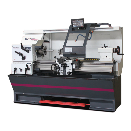
OPTIMUM Maschinen OPTIturn TX 4414 Manuals
Manuals and User Guides for OPTIMUM Maschinen OPTIturn TX 4414. We have
1
OPTIMUM Maschinen OPTIturn TX 4414 manual available for free PDF download: Operating Manual
OPTIMUM Maschinen OPTIturn TX 4414 Operating Manual (138 pages)
Brand:
OPTIMUM Maschinen
| Category:
Lathe
| Size: 6.78 MB
Table of Contents
Table of Contents
2
1 Safety
7
Rating Plate
7
Safety Instructions (Warning Notes)
8
Classification of Hazards
8
Other Pictograms
8
Intended Use
9
Reasonably Foreseeable Misuses
10
Avoiding Misuse
10
Potential Dangers that Can be Caused by the Lathe
10
Qualification of Personnel
11
Target Group
11
Authorized Persons
12
Obligations of the Operating Company
12
User's Obligations
12
Additional Requirements Regarding the Qualification
12
Operator Positions
13
Safety Measures During Operation
13
Safety Devices
13
Lockable Master Switch
14
Emergency-Stop Button
14
Protective Cover of the Headstock
14
Protective Covers of Drive
14
Lathe Chuck Protection with Position Switch
14
Chip Guard Shield
15
Prohibition, Warning and Mandatory Signs
15
Safety Check
15
Personal Protective Equipment
17
Safety During Operation
17
Safety During Maintenance
18
Disconnecting and Securing the Lathe
18
Using Lifting Equipment
18
Mechanical Maintenance Work
18
Accident Report
18
Electronics
19
Inspection Deadlines
19
2 Technical Specification
20
Electrical Connection
20
Power
20
Work Areas
20
Work Area
20
Headstock
20
Lathe Chuck
20
Slides
20
Feeds and Pitches
20
Emissions
21
Tailstock MT4
21
Tailstock MT5 Version
21
Steady Rest, Follow Rest (Option)
21
Dimensions
21
Environmental Conditions
21
Operating Material
21
3 Delivery, Interdepartmental Transport, Assembly and Commissioning
23
Notes on Transport, Installation, Commissioning
23
General Risks During Internal Transport
23
Delivery
24
Unpacking
24
Lifting the Machine
24
Forklift
24
Crane
25
Installation Conditions
26
Foundation and Floor
26
Local Requirements for Delivery
26
Installation Plan
27
Assembly and Installation, Initial Operation
27
Anchor-Free Assembly
28
Installation with Levelling- Damping Elements
28
Installation with Vibration Dampers
28
Anchored Assembly
30
Aligning the Machine
31
Cleaning the Machine
32
Lubrication
32
One-Component Paint
32
Electrical Connection
33
Start and Stop Spindle Rotation
33
Warming up the Machine
33
4 Operation
34
Control and Indicating Elements
34
Safety
35
Switching on the Machine
35
Switching off the Machine
35
Resetting an Emergency Stop Condition
35
Power Failure, Restoring Readiness for Operation
35
Foot Brake
35
Speed Setting
35
Rotational Direction
36
Feed
37
Bed Slide and Cross Slide Rapid Traverse
38
Spindle Seat Camlock DIN ISO 702-2
38
Fasten Workpiece Holder
38
Adjusting the Camlock Bolts to the Workpiece Holder
39
Lathe Chuck
39
Influencing Factors that Significantly Impact the Tensioning Force
40
Maintenance of Chucks
41
Clamping a Workpiece into the Lathe Chuck
41
Clamping Long Workpieces
43
Mounting Workpiece Holder
44
Centering Point in Lathe Spindle
44
Mounting of Rests
44
Follow Rest and Steady Rest
44
General Operating Instructions
44
Longitudinal Turning
44
Face Turning and Recessing
45
Fixing the Lathe Saddle
45
Tailstock
45
Manual Movements
45
Automatic Feed
46
Straight Turning
46
Face Turning
47
Turning Tapers
47
Cross-Adjustment of the Tailstock
47
Turning Short Tapers with the Top Slide
48
Turning of Cones with High Precision
48
Displacing the Top Slide on the Cross Slide
51
Standard Values for Cutting Data When Turning
51
Thread Cutting
52
Module and D
52
Multiple-Layered Threads
54
Thread Types
54
Metric Threads (60° Flank Angle)
56
British Thread (55° Flank Angle)
57
Indexable Inserts
59
Cooling Lubricant
60
Cooling Lubricants
60
DP700 Quick Start Guide
62
NMS300 Quick Start Guide
65
5 Cutting Speeds
68
Selecting the Cutting Speed
68
Influences on the Cutting Speed
68
Example for the Determination of the Required Speed on Your Lathe
68
6 Maintenance
70
Safety
70
Preparation
70
Restarting
71
Inspection and Maintenance
71
Recommended Wearing Parts
75
Maintenance
76
Tensioning of Drive Belt
76
Refilling the Cooling Lubricant
76
Replacement of the Shear Pin on the Feed Rod
76
Adjusting the Spindle Nut on the Top Slide
77
Adjusting the Spindle Nut on the Cross Slide
78
Adjusting the Tapered Gibs on the Top Slide and Cross Slide
78
Lathe Saddle
78
Apron
78
Feed Rod, Lead Screw
79
Lubricating and Cleaning the Lathe Chuck
79
Cleaning the Electrical Cabinet
79
Aligning the Headstock
80
Repair
81
Customer Service Technician
81
Cooling Lubricants and Tanks
82
Inspection Plan for Water-Mixed Cooling Lubricants
83
7 Rotary Chuck - K11-200 ISO
84
Safety Instructions
85
Intended Use
85
Reasonably Foreseeable Misuses
85
Avoiding Misuse
85
Basic Safety Instructions
86
Optional Soft Lathe Chuck Jaws
86
Calculating the Required Clamping Force for a Given Speed
87
Clamping Force-Speed Diagram - Lathe Chuck K11-200
88
Clamping Jaw Centrifugal Force
88
Notes on Instruction of Operating Personnel
90
Scope of Delivery
90
Assembly
91
Assembly of the Manual Chuck
91
Handling before Mounting
91
Preparing the Chuck Attachment
91
Mounting of the Manual Chuck
91
Lubricating and Cleaning the Lathe Chuck
91
8 Ersatzteile - Spare Parts
92
Ersatzteilbestellung - Ordering Spare Parts
92
Hotline Ersatzteile - Spare Parts Hotline
92
Service Hotline
92
Ersatzteilzeichnungen - Spare Part Drawings
93
A Spindelgetriebe - Spindle Gear
93
B Spindelgetriebe - Spindle Gear
94
C Spindelgetriebe - Spindle Gear
95
D Spindelgetriebe - Spindle Gear
96
E Vorschubgetriebe - Feed Gear
100
F Vorschubgetriebe - Feed Gear
101
G Vorschubgetriebe - Feed Gear
102
H Schlosskasten Handrad Links - Apron Hand Wheel Left Side
106
I Planschlitten, Bettschlitten - Cross Slide, Bed Slide
109
J Oberschlitten - Top Slide
111
K Maschinenbett Kurz mit Bettbrücke - Short Machine Bed with Bed Bridge
113
U Maschinenbett Lang ohne Bettbrücke - Long Machine Bed Without Bed Bridge
114
L Maschinenbett - Machine Bed
115
Maschinenbett - Machine Bed
116
N Reitstock - Tailstock
118
O Drehfutterschutz - Lathe Chuck Protection
120
P Mitlaufende Lünette - Follow Rest
121
Q Feststehende Lünette - Steady Rest
122
R Schaltplan - Wiring Diagram
123
S Schaltplan - Wiring Diagram
124
T Schaltplan - Wiring Diagram
125
9 Malfunctions
129
10 Appendix
131
Copyright
131
Terminology/Glossary
131
Change Information Operating Manual
131
Liability Claims/Warranty
132
Storage
133
Dismantling, Disassembling, Packing and Loading
133
Decommissioning
134
Dismantling
134
Disassembly
134
Packing and Loading
134
Disposal of New Device Packaging
134
Disposal of Lubricants and Cooling Lubricants
134
Disposal Via Municipal Collection Facilities
135
Product Follow-Up
135
Advertisement
Advertisement
Related Products
OPTIMUM Maschinen OPTIturn 3432420
OPTIMUM Maschinen Categories
Drill
Industrial Equipment
Grinder
Sander
Lathe
More OPTIMUM Maschinen Manuals
Login
Sign In
OR
Sign in with Facebook
Sign in with Google
Upload manual
Upload from disk
Upload from URL