Sign In
Upload
Manuals
Brands
Omnitracs Manuals
Touchscreen
MCP110
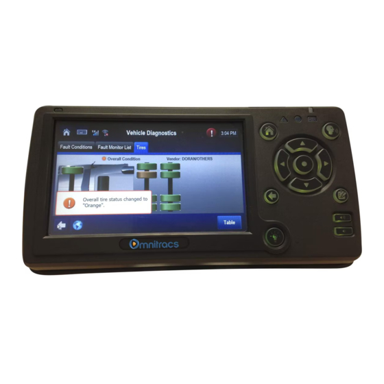
Omnitracs MCP110 Manuals
Manuals and User Guides for Omnitracs MCP110. We have
2
Omnitracs MCP110 manuals available for free PDF download: Diagnostics Manual, Installation Manual
Omnitracs MCP110 Installation Manual (212 pages)
Brand:
Omnitracs
| Category:
Touchscreen
| Size: 12 MB
Table of Contents
Table of Contents
3
Important Safety Information
9
Safety Definitions
9
Safety Advice
9
How the MCP110 Works MCP110 Overview
12
Why MCP110 Makes Companies more Efficient
12
MCP110 Component Description
13
CDMA Wireless Network
14
GPS Network
14
MCP110 Mobile Components
15
Component Overview
17
Wireless Interface Box 110 (WIB110)
19
Display Interface Unit 110 (DIU110)
19
Mobile Application Server 110 (MAS110)
20
Backup Battery
20
Optional Parts
21
Wib200
21
Diu200
21
Optional Accessories/Applications for the MCP110
21
General Wiring and Installation Guidelines
23
Making Electrical Connections
24
Approved Omnitracs Electrical Connectors
24
Wire Stripping
24
Butt Splicing
25
Crimping
26
Ring Terminals
32
Proper Grounding
32
General Installation Guidelines
33
Routing and Protecting Cables
33
Installation Planning
37
Installation Guidelines
38
Safety, Reliability, and Accessibility
38
Typical Installation Sequence
38
Typical Installation Locations for MCP110 Components
39
Conventional Vehicle Types
40
Straight Truck Vehicle Types (All Makes)
45
Cabover Engine Vehicle Types (All Makes)
46
Special Cable Ordering Instructions for Tilt Cabs
46
Tools and Supplies Recommended for Installations
47
Omnitracs Approved Sealants
47
Mobile Application Server 110 (MAS110) Installation
50
General Installation Guidelines
50
Installing the Backup Battery into the MAS110
50
Installing the MAS110
51
Selecting a Mounting Location
51
Securing the MAS110
52
Installing the Power Cable
53
Low Voltage Disconnects (Lvds)
53
Power Cable Run
53
Power Cable Routing
53
Power Cable Wire Connections
53
Grounding Guidelines
54
Installing the Accessory Cable
55
Cable Run
56
Connecting Cables to the MAS110
56
Wireless Interface Box 110 (WIB110) Antenna Installation
57
General Installation Guidelines
58
WIB Antenna View-Of-Sky Requirements
58
Installation of WIB Mount
59
Option #1
59
Option #2
59
Mount the WIB Antenna
61
Routing the WIB Cable
61
Connecting the Antenna Cable to the MAS110
61
Display Interface Unit 110 (DIU110) Installation
63
General Installation Guidelines
64
Selecting a Mounting Location
64
Installing the Display Holster and Display
67
Display Cable Routing
67
Connecting the Display Cable to the DIU110
68
Inserting the DIU110 into the Holster
69
Connecting the Display Cable to the MAS110
69
Text-To-Speech (TTS) Installation
71
General Installation Guidelines
72
Selecting a Speaker
72
Speaker Requirements
72
Choosing a Speaker
72
Option 1-Connecting to an Existing or Shared Speaker
73
Connecting Speaker Switch Cable to Accessory Cable
74
Option 2-Connecting to a Dedicated 8-Ohm Speaker
76
Vehicle Data Bus Connections
77
Vehicle Data Source Overview
78
J1939 Data Bus
78
J1708/J1587 Data Bus
78
Traditional Sensors
78
Overview
78
Vehicle Data Source Selection
79
Guidelines for Connecting to the J1939 Data Bus
79
Selection
79
J1939 Pre-Installation Check out
80
Resistance Test (to Verify that J1939 Is Present)
80
J1939 Pre-Installation Check
80
Out
80
Option 1-Connecting J1939 Using the Repeater Cable
81
Making the Connection
81
Option 1-Connecting J1939 Using the Repeater
81
Cable
83
Option 2-Connecting J1939 Without Using the Repeater Cable
84
Making the Connection
85
Connecting J1708 /J1587
86
Verifying Data Source Connectivity
88
System Verification
91
What Is Basic MCP110 System Verification
92
How to Find the MCP110 Unit Address (UA)
92
Performing System Verification
93
MCP110 Diag Screen
94
Flowchart-Basic MCP110 System Verification
96
Basic MCP110 System Verification Procedure
98
MCP System Screens
102
MCP110 System Screen
102
MCP110 Comm Screen
103
MCP110 GPS Screen
104
MCP110 Performance Screen
105
VDS Screen
106
Omnitracs MCP110 System Verification Form
106
Performance Monitoring System Verification
109
Performance Monitoring System Overview
110
Performance Monitoring System Verification
110
Input Screen Example
111
Understanding Performance Monitoring Faults
111
Other Performance Monitoring System Display Screens
114
Summary Screen
114
Performance Screen
115
Violations Screen
116
Parameters Screen
117
PTO Screen
118
Odometer Screen
119
Special Alert Display Messages
120
Warning Messages
120
Power Take-Off (PTO) Overview
120
PTOP (Power Take-Off Pump)/Ptoc (Power Take-Off Compressor)
121
PTO Data Input Verification Procedure
122
Vehicle Maintenance System Verification
123
Vehicle Maintenance Overview
124
Feature Requirements
124
Connecting the J1939 Wires
124
Vehicle Maintenance System Verification
125
Critical Event Reporting System Verification
127
CER Overview
128
CER System Verification
129
Identify Configuration and Available CER Features
129
Test System by Manually Reporting an Event
133
Trailer Management System Installation
135
Trailer Management System Overview
136
Hardware Requirements
136
Trailer Management System Wiring for the Truck
136
Fuse Kit Installation
136
Trailer Management System Verification
137
Enabling the Option for the Trailer Management System
137
Trailer Connection/Disconnection
138
Trailer Management Diagnostic Screen
139
Refrigeration Status Screen
140
Wired Panic Button Installation
143
Wired Panic Button Overview
143
Installing the Panic Button
144
Installation Verification
146
Automated Panic Button Test System Dial-In Procedure
146
Wireless Panic Button Installation
147
Overview
147
Wireless Panic Button Kit
148
Additional Wireless Panic Button Accessories
149
Tools and Supplies Needed for Installation
149
Using the Remote Transmitter
150
Activating the PANIC Feature
150
Activating the AUX Feature
150
TEST/RESET Feature
151
Activating the LOCK/UNLOCK Button
151
Wireless Panic Button Receiver Installation
151
Wireless Panic Button Wiring
151
Panic Wire Installation
152
Voltage Check
154
Antenna Installation
154
Antenna Placement
155
Antenna Cable Routing and Connection
155
Final Connection
156
Installation Verification for the Wireless Panic Button
156
Wireless Panic Button Battery
157
Wireless Panic Button Battery Replacement
158
In-Cab Scanner Installation
161
Installation Guidelines
162
Mounting the Scanner
162
Scanner Mounting Option (Without the Holster)
162
Holster Mounting Option
163
Installing the Scanner
163
Calibrating the Scanner
163
Scanner
163
Sending a Scan
164
Cleaning the Scanner
165
Return Material Authorization (RMA) Process for Scanners
165
Scanner
165
BCS Solutions Scanner Parts List
166
Appendix A Wiring Diagrams and Charts
168
MCP110 Electrical Diagram
168
MCP110 Wiring Diagram
169
Power Cable Connector Pin Callouts
170
Wireless Interface Box (WIB110) Cable Connector Pin Callouts
171
Primary Accessory Cable Connector Pin Callouts
172
MCP100 to MCP200 Accessory Adapter Cable
173
Display Interface Unit 110 (DIU110) Cable Connector Pin Callouts
174
Six-Pin Data Link Connector Pin Callouts
175
Nine-Pin Data Link Connector Pin Callouts
176
Radio Connector Pin Callouts
177
CAN Repeater Cable Pin Callouts
178
Speaker Switch Cable
179
Appendix B Environmental and Power Requirements
181
MCP110 Environmental and Power Requirements
182
Appendix C Standard RMA Procedure
183
Appendix D Upgrading the MCP110 Using USB Memory Sticks
185
Checking the Software Versions Installed
186
Upgrading Only the MAS110 Software
186
Upgrading the MAS os and MAS Software
187
Appendix E Preventive Maintenance Inspection
192
How Often Should Inspections be Performed
192
Inspecting the Mobile Application Server 110 (MAS110
192
Inspecting the Display Interface Unit 110 (DIU110
194
Inspecting the Antennas
196
Verifying Trailer Management System Connections
197
Appendix F Component and Document Information
201
Dcns for Documents Referenced in this Guide
202
MCP110 System Component Mcns Referenced in this Guide
202
Mcns for Sealants and Lubricants Referenced in this Guide
206
MCN for Other Items
206
Appendix G Glossary
207
Advertisement
Omnitracs MCP110 Diagnostics Manual (214 pages)
Brand:
Omnitracs
| Category:
Control Systems
| Size: 13 MB
Table of Contents
Section 1
3
Table of Contents
3
Important Safety Information
9
Safety Definitions
9
Safety Advice
9
Section 2
11
Chapter 1 How the MCP110 Works
12
MCP110 Overview
12
Why MCP110 Makes Companies more Efficient
12
MCP110 Component Description
13
CDMA Wireless Network
14
Wifi Network (Optional)
14
GPS Network
15
Optional Data Satellite
15
MCP110 Mobile Components
15
Chapter 2 Best Practices
17
For Technical Questions, Contact Omnitracs Customer Support
17
Customer Support Is Staffed 24 Hours a Day, 365 Days a Year
17
In Canada, Call 800-863-9191
17
In the United States, Call 800-541-7490
17
Troubleshooting Guidelines
18
Keep Known Good MCP110 Component Spares in Shop
18
Perform a Visual Inspection of the Installed MCP110
19
Reseat All Cables
19
Use a Test Cart to Perform Bad Part Verification/Double Checking
19
Verify MAS110 LED Indicators Are in a Normal State
19
Check System Voltage Measurements and Grounding
20
Determine if the Problem Is Intermittent
20
Install Parts Correctly
20
Replace Only Faulty Parts
20
Preventive Maintenance Inspection
21
Chapter 3 Preventive Maintenance Inspection
22
How Often Should Inspections be Performed
22
Inspecting the Mobile Application Server 110 (MAS110)
22
Inspecting the Display Interface Unit 110 (DIU110)
24
Inspecting the Antennas
26
Verifying Trailer Management System Connections
27
System Verification
31
Customer Support Is Staffed 24 Hours a Day, 365 Days a Year
31
For Technical Questions, Contact Omnitracs Customer Support
31
In the United States, Call 800-541-7490
31
Chapter 4 System Verification
32
How to Find the MCP110 Unit Address (Ua)/Serial Number
32
What Is Basic MCP110 System Verification
32
Performing System Verification
33
Flowchart-Basic MCP110 System Verification
34
Basic MCP110 System Verification Procedure
36
MCP System Screens
40
MCP110 System Screen
40
MCP110 Comm Screen
41
MCP110 GPS Screen
42
MCP110 Performance Screen
43
MCP110 Diag Screen
44
VDS Screen - Details
45
VDS Screen - Summary
45
Omnitracs MCP110 System Verification Form
45
Display Problem Troubleshooting
47
Chapter 5 Display Problem Troubleshooting
48
DIU110 Overview
48
Normal Performance
48
Display Problem Troubleshooting
48
Abnormal Performance
49
DIU110 Display Touchscreen Lighting
49
DIU110 Touchscreen Non-Responsive/Calibration
50
DIU110 Screen Is Dark or Blank
51
DIU110 Stuck on Loading Screen or Error Message at Bootup
55
Chapter 6 Connectivity Problem Troubleshooting
57
For Technical Questions, Contact Omnitracs Customer Support
57
Customer Support Is Staffed 24 Hours a Day, 365 Days a Year
57
In Canada, Call 800-863-9191
57
In the United States, Call 800-541-7490
57
Overview
58
Normal Performance
58
Abnormal Performance
58
NO SIGNAL Light on or Flashing
59
Cannot Send/Receive
64
MCP110 Cannot Send/Receive
65
Low Cellular/Terrestrial Signal Strengths
68
How to Check the RSSI Value
68
Materials that Obstruct the Signal (Cellular and GPS)
68
What Is the RSSI Value
68
Gps Positioning Problem Troubleshooting
69
Chapter 7 GPS Positioning Problem Troubleshooting
70
GPS Positioning System
70
Normal Performance
70
Abnormal Performance
71
GPS Positioning
72
Wifi Problem Troubleshooting (Optional)
77
Chapter 8 Wifi Problem Troubleshooting (Optional)
78
Wifi Overview
78
Wifi Problem Troubleshooting (Optional)
78
Normal Performance
79
Abnormal Performance
79
Steps to Resolve Access Problems
79
Identifying When Wifi Coverage Is Available
79
Open Wifi - How Access Is Granted to the Unit
79
Configuring Wifi Web Browsing
80
Chapter 9 Miscellaneous Problem Troubleshooting
83
For Technical Questions, Contact Omnitracs Customer Support
83
Customer Support Is Staffed 24 Hours a Day, 365 Days a Year
83
In Canada, Call
83
In the United States, Call 800-541-7490
83
Application Icons Not Available - Grayed-Out
84
Display Immediately Goes Blank When Ignition Is Turned off
84
MCP110 Does Not Go to Ignition off
84
Chapter 10 MAS110 Status-LED Indicators
85
MAS110 Performance-LED Indicators
86
No Power to MAS110-Leds OFF/OFF
87
Text-To-Speech Problem Troubleshooting
91
Chapter 11 Text-To-Speech Problem Troubleshooting
92
Text-To-Speech Overview
92
Speaker Requirements
92
Normal Performance
92
Abnormal Performance
93
Message Does Not Play
93
Message Plays but Volume Is very Low
93
Message Plays but Volume Is very Low
100
Message Plays but Sound Is Choppy or Breaks up
105
Backup Battery Troubleshooting
111
Chapter 12 Backup Battery Troubleshooting
112
About the MAS110 Backup Battery
112
Backup Battery Troubleshooting
112
Good Status
113
Bad Status
113
Manually Testing the Backup Battery
114
Bad Backup Battery
115
Chapter 13 Database out of Sync
117
For Technical Questions, Contact Omnitracs Customer Support
117
Customer Support Is Staffed 24 Hours a Day, 365 Days a Year
117
In Canada, Call 800-863-9191
117
In the United States, Call 800-541-7490
117
Good Status
118
Bad Status
118
What to Do
118
Database State will Not Go to Sync Complete
118
Vehicle Data Link Diagnostic/Verification Procedures
119
Chapter 14 Vehicle Data Link Diagnostic/Verification Procedures
120
Vehicle Data Services (VDS) Overview
120
Vehicle Data Link Verification
121
J1708/J1587 Flowchart
124
J1939 Flowchart
127
Chapter 15 Performance Monitoring
131
Diagnostic/Verification Procedures
131
Normal Performance
132
System Overview
132
Input Screen Example
133
Understanding Performance Monitoring Faults
134
Abnormal Performance
136
Diagnostic Flowchart for Data Not Available
136
Diagnostic Procedure for Data Not Available
137
Chapter 16 Trailer Tracks Asset Management Diagnostic/Verification Procedures
141
Normal Performance
142
Abnormal Performance
142
Trailer Tracks Asset Management System Verification
143
A-Transmitter ID Not Displayed
147
A1-+12/24 VDC Is Not at Pigtail
152
B-Reefer Status Number Not Incrementing
154
Chapter 17 Critical Event Reporting
158
Overview
158
Normal Performance
158
Abnormal Performance
158
Event Not Triggered
158
CER Verify Configuration
158
CER Verify Data Link
160
Sending a CER Event
160
Events Triggered in Error
161
Chapter 18 Vehicle Maintenance
164
Overview
164
Normal Performance
164
Abnormal Performance
164
Verify Configuration Settings
165
Verify Data Link Connections to Connect to J1939 Data Link
165
Panic Button Diagnostic Procedures
169
Chapter 19 Panic Button Diagnostic Procedures
170
Normal Performance
170
Abnormal Performance
170
Panic Button Diagnostic Procedures
170
False Panic Message
171
No Panic Message
174
In-Cab Scanner Diagnostic Procedures
179
Chapter 20 In-Cab Scanner Diagnostic Procedures
180
Overview
180
Normal Performance
180
Abnormal Performance
180
RMA Process
180
In-Cab Scanner Diagnostic Procedures
180
Troubleshooting
181
Wiring Diagrams and Charts
183
Customer Support Is Staffed 24 Hours a Day, 365 Days a Year
183
In Canada, Call 800-863-9191
183
In the United States, Call 800-541-7490
183
For Technical Questions, Contact Omnitracs Customer Support
183
Appendix A Wiring Diagrams and Charts
184
Omnitracs MCP110 Electrical Diagram
184
Topics in this Appendix Provide Wiring Diagrams and Pin Description Charts for the Omnitracs
184
Omnitracs MCP110 Wiring Diagram
185
Power Cable Connector Pin Callouts
186
Wireless Interface Box (WIB) Cable Connector Pin Callouts
187
Speaker Switch Cable
188
MCP100 to MCP200 Accessory Adapter Cable
190
Display Interface Unit 110 (DIU110) Cable Connector Pin Callouts
191
Six-Pin Data Link Connector Pin Callouts
192
Nine-Pin Data Link Connector Pin Callouts
193
Radio Connector Pin Callouts
194
CAN Repeater Cable Pin Callouts
195
CAN Repeater Cable Pin Callouts
196
Appendix B Environmental and Power Requirements
197
MCP110 Environmental and Power Requirements
198
Appendix C Standard RMA Procedure
199
Appendix D Upgrading the MCP110 Using USB Memory Sticks
201
Checking the Software Versions Installed
202
Upgrading Only the MAS110 Software
203
Upgrading the MAS os and MAS Software
204
Glossary
209
Advertisement
Related Products
Omnitracs MCP50
Omnitracs MCP100
Omnitracs Categories
Automobile Accessories
GPS
Gateway
Digital Camera
Car Receiver
More Omnitracs Manuals
Login
Sign In
OR
Sign in with Facebook
Sign in with Google
Upload manual
Upload from disk
Upload from URL