Table of Contents
Advertisement
Quick Links
Advertisement
Chapters
Table of Contents
Troubleshooting

Related Manuals for Omnitracs MCP110

Summary of Contents for Omnitracs MCP110
- Page 1 MCP110 Diagnostic Guide 80-JB423-1 Rev. F October 2015...
- Page 2 Omnitracs endeavors to ensure that the information in this document is correct and fairly stated, but Omnitracs is not liable for any errors or omissions. Published information may not be up to date, and it is important to confirm current status with Omnitracs.
-
Page 3: Table Of Contents
Chapter 2 Best Practices Troubleshooting Guidelines ..................2-2 Keep Known Good MCP110 Component Spares in Shop ........2-2 Use a Test Cart to Perform Bad Part Verification/Double Checking ....2-3 Perform a Visual Inspection of the Installed MCP110 .......... 2-3 Reseat All Cables .................... - Page 4 Chapter 4 System Verification What Is Basic MCP110 System Verification? .............. 4-2 How to Find the MCP110 Unit Address (UA)/Serial Number ........4-2 Performing System Verification ................... 4-3 Flowchart—Basic MCP110 System Verification ............4-4 Basic MCP110 System Verification Procedure ............4-6 MCP System Screens ....................
- Page 5 Chapter 9 Miscellaneous Problem Troubleshooting Application Icons Not Available - Grayed-out .............. 9-2 Display Immediately goes Blank when Ignition is Turned Off ........9-2 MCP110 Does Not Go to Ignition Off ................9-2 Chapter 10 MAS110 Status—LED Indicators MAS110 Performance—LED Indicators ..............10-2 No Power to MAS110—LEDs OFF/OFF ..............
- Page 6 Chapter 14 Vehicle Data Link Diagnostic/Verification Procedures Vehicle Data Services (VDS) Overview ..............14-2 Vehicle Data Link Verification ..................14-3 J1708/J1587 Flowchart ..................... 14-6 J1939 Flowchart ......................14-9 Chapter 15 Performance Monitoring Diagnostic/Verification Procedures System Overview ....................... 15-2 Normal Performance ....................15-2 Input Screen Example ..................
- Page 7 Appendix B Environmental and Power Requirements MCP110 Environmental and Power Requirements ............. B-2 Appendix C Standard RMA Procedure Appendix D Upgrading the MCP110 Using USB Memory Sticks Checking the Software Versions Installed ..............D-2 Upgrading Only the MAS110 Software ................D-3 Upgrading the MAS OS and MAS Software ..............D-4 Glossary 80-JB423-1 Rev.
- Page 8 viii 80-JB423-1 Rev. F MAY CONTAIN U.S. AND INTERNATIONAL EXPORT CONTROLLED INFORMATION...
-
Page 9: Important Safety Information
If you are a Third-party Device Manufacturer or Application Developer, it is your responsibility to provide appropriate warnings regarding the safe use of your device(s) in conjunction with Omnitracs equipment. Applications should not require the driver to divert his attention from the road while driving a vehicle. - Page 10 80-JB423-1 Rev. F MAY CONTAIN U.S. AND INTERNATIONAL EXPORT CONTROLLED INFORMATION...
- Page 11 ..........Why MCP110 Makes Companies More Efficient .
-
Page 12: Chapter 1 How The Mcp110 Works
How the MCP110 Works MCP110 Overview MCP110 is a high bandwidth mobile computing platform designed to help increase customer service, reduce operating costs, enhance driver productivity, and ensure vehicle safety. MCP110 offers cellular connectivity, optional WiFi, and delivers more processing power on ®... -
Page 13: Mcp110 Component Description
• Within the NOC is the Network Management Computer (NMC), which receives and handles information traffic. • Located at Omnitracs, LLC in Las Vegas, NV. Omnitracs Dispatch • Software on the trucking company’s dispatch computer and dispatcher’s interface with the MCP110. -
Page 14: Cdma Wireless Network
Omnitracs NOC where it is distributed to the dispatch center. Dispatchers respond by sending a notification back to the Omnitracs NOC, where it is relayed to the PCS gateway and broadcast out to the wireless network to be picked up by the vehicle’s antenna. -
Page 15: Gps Network
• Mobile part of the Omnitracs platform is installed in a customer’s vehicle. • Each MCP110 has its own unique unit address which is the serial number on the MAS110. This address is used to route information to the correct vehicle. - Page 16 - Mobile application server (MAS110)—Unit which contains the operating circuitry and memory for the MCP110. The “black box” of the platform. - Display interface unit (DIU110)—Standard display unit for the MCP110, which the driver uses to connect with the dispatcher. Consists of a color graphical display that integrates touchscreen functionality, extended temperature range, and improved clarity for drivers.
-
Page 17: Chapter 2 Best Practices
......... . . For technical questions, contact Omnitracs Customer Support. -
Page 18: Troubleshooting Guidelines
Troubleshooting Guidelines Best Practices Troubleshooting Guidelines Keep Known Good MCP110 Component Spares in Shop Spare parts should include: • Mobile Application Server (MAS110) • MAS backup battery • Wireless Interface Box (WIB110) • WIB110 cable • Display Interface Unit (DIU110) •... -
Page 19: Use A Test Cart To Perform Bad Part Verification/Double Checking
Use a Test Cart to Perform Bad Part Verification/Double Checking If a Omnitracs MCP110 part is diagnosed bad on a truck, insert the failed part on the test cart. • If it continues to fail, the RMA process should be utilized to replace the part. -
Page 20: Check System Voltage Measurements And Grounding
Install Parts Correctly Refer to the MCP110 Installation Guide. Determine If the Problem Is Intermittent Check for: •... - Page 21 ......For technical questions, contact Omnitracs Customer Support. Customer Support is staffed 24 hours a day, 365 days a year: •...
-
Page 22: How Often Should Inspections Be Performed
How Often Should Inspections Be Performed? Preventive Maintenance Inspection How Often Should Inspections Be Performed? • Omnitracs recommends inspections be performed at least once every 90 days. • During normally scheduled vehicle preventive maintenance inspections. Inspecting the Mobile Application Server 110 (MAS110) - Page 23 Preventive Maintenance Inspection Inspecting the Mobile Application Server 110 (MAS110) Make sure the cable connectors have not worked themselves loose from the MAS110. Hand tighten any thumb screw connectors. Verify that the strain relief bracket is installed and cables are secure. Caution DO NOT apply grease to the connectors.
-
Page 24: Inspecting The Display Interface Unit 110 (Diu110)
• Turn the IGN to the OFF position and verify that the status goes to Ignition Off. Verify the DIU110 screen are clean. Omnitracs recommends that you use a soft cloth and either plain water, glass cleaner, or mild soap to gently clean the surfaces of the DIU110 as well as the display screen. - Page 25 Preventive Maintenance Inspection Inspecting the Display Interface Unit 110 (DIU110) Make sure the display cable has enough slack and is not being rubbed or cut by anything inside the cab. Remove the DIU110 from the holster and make sure the screws holding the holster in place are secure.
-
Page 26: Inspecting The Antennas
Inspecting the Antennas Preventive Maintenance Inspection Inspecting the Antennas Make sure all cables are protected with convoluted tubing and are in good condition. Wireless Interface Box (WIB) Make sure cables have no kinks or bends and are not being pulled tightly against metal edges that can rub or cut the cables. -
Page 27: Verifying Trailer Management System Connections
0ME-0128-18A Verifying Trailer Management System Connections Make sure all 7-way connection points have been cleaned, inspected, and greased. Omnitracs recommends that you use dielectric grease on the connection points. Brushes 04AAA_164A 80-JB423-1 Rev. F MAY CONTAIN U.S. AND INTERNATIONAL EXPORT CONTROLLED INFORMATION... - Page 28 Verifying Trailer Management System Connections Preventive Maintenance Inspection Check the 7-way coil cord for nicks, cuts, or abrasions. Replace the cord as necessary. 04AAA_161 80-JB423-1 Rev. F MAY CONTAIN U.S. AND INTERNATIONAL EXPORT CONTROLLED INFORMATION...
- Page 29 Preventive Maintenance Inspection Verifying Trailer Management System Connections Make sure there is voltage (12–24V) on pin 7 at all 7-way connection points (on the tractor and trailer). Make sure you connect to ground (pin 1) as Receptacle well when performing this step. The illustrations at left show the connection at the tractor and at the trailer.
- Page 30 Verifying Trailer Management System Connections Preventive Maintenance Inspection Connect a test transmitter to the truck. Turn IGN to ON. Touch the Trailer Management button to access the Trailer IDs screen and verify that the transmitter’s ID displays. Test with known, Trailer Tracks good Trailer Tracks Transmitter...
-
Page 31: For Technical Questions, Contact Omnitracs Customer Support
Verification?......How to Find the MCP110 Unit Address (UA)/Serial Number .... -
Page 32: What Is Basic Mcp110 System Verification
System button, then tap the button. Tap the System tab. The MCP110 Unit Address is at the top of the page. The MAS also has the Unit Address written on the yellow label. -
Page 33: Performing System Verification
System Verification Performing System Verification Performing System Verification • Shortly after you power up the MCP110, the MCP110 Home screen displays. • System verification information has been stored on screens/buttons under the System button. • Tap the left or right arrow to get to the System button. Tap the button to access the display screens shown on the following pages. -
Page 34: Flowchart-Basic Mcp110 System Verification
Flowchart—Basic MCP110 System Verification System Verification Flowchart—Basic MCP110 System Verification Step 1 Turn ignition Step 2 Display Diag screen. Run ALL tests. Step 3 See the appropriate chapter: Cellular refer to Chapter 6 CDD refer to Chapter 13 GPS refer to Chapter 7... - Page 35 System Verification Flowchart—Basic MCP110 System Verification Step 7 See Chapter 6 Was test Communication message received Problem at MCP110? Troubleshooting Step 8 See Chapter 11 Tap Home button. Text-to-Speech Does TTS play? Problem Troubleshooting See Chapter 14 Verify Vehicle Vehicle Data Link...
-
Page 36: Basic Mcp110 System Verification Procedure
• At minimum, Cellular, CDD database, GPS, and Battery Backup should show green checkmarks. • If the MCP110 passed all the tests, go to step 4. • If the MCP110 failed any necessary tests, go to the appropriate diagnostic procedure for the failed item in this guide. - Page 37 System Verification Basic MCP110 System Verification Procedure Send a test message to the dispatcher. Go to the Home screen and tap the Messaging button. • Tap the Compose tab. • Type the message text including the truck number. • Send the message? •...
- Page 38 Waiting Light should come on, and a voice notification will tell you the message has been received. Tap the Inbox tab to display the dispatcher’s message. • If the MCP110 received the message, go to step 8. • If the MCP110 did not receive the message, see...
- Page 39 System Verification Basic MCP110 System Verification Procedure Turn the vehicle ignition OFF. Turn the ignition OFF Make sure the display unit stays on with the ignition OFF. • If the display unit stays on, go to step 11. • If the display unit does not stay on, see...
-
Page 40: Mcp System Screens
MCP110 and is up-to-date. This is the desired state. • Out of sync is displayed if the mobile unit (MCP110) information has not been received by the MCP110 and is waiting to be updated. -
Page 41: Mcp110 Comm Screen
System Verification MCP110 Comm Screen MCP110 Comm Screen • Tap the Comm tab to access antenna information about the MCP110. • This screen displays antenna information on the WIB110 (cellular and optional WiFi). Field Description Satellite (applies only if SDM is installed) Active/In Use Green light shown when mode type is available. -
Page 42: Mcp110 Gps Screen
The last received longitude value. Altitude The last received altitude value. Mode Indicates the MCP110’s GPS status: • 3-D is displayed if the receiver is able to view three or more GPS satellites. Under normal performance, a 3-D mode will be displayed. -
Page 43: Mcp110 Performance Screen
System Verification MCP110 Performance Screen MCP110 Performance Screen • Tap the Performance tab whenever you want to see the basic configuration of the unit. Field Description Shows MAS110 CPU usage. Memory Amount of memory used. Disk Amount of flash memory space used. -
Page 44: Mcp110 Diag Screen
System Verification MCP110 Diag Screen • The Run All button, located at the bottom right of the screen. The system runs tests of all possible connections to the MCP110 and then displays whether the connection is found (green ), or not found (red X). -
Page 45: Vds Screen - Summary
Omnitracs MCP110 System Verification Form You can make copies of the System Verification Form on the following page and record important information you may want to keep concerning the vehicle and the MCP110. 80-JB423-1 Rev. F 4-15 MAY CONTAIN U.S. AND INTERNATIONAL EXPORT CONTROLLED INFORMATION... - Page 46 Omnitracs MCP110 System Verification Form System Verification Installation Verification Form - MCP110 ‰ ‰ ‰ ‰ ‰ ‰ I find the service rendered and materials installed in connection with the above mentioned work to have been completed in a satisfactory manner.
- Page 47 DIU110 Stuck on Loading Screen or Error Message at Bootup ....For technical questions, contact Omnitracs Customer Support. Customer Support is staffed 24 hours a day, 365 days a year: •...
-
Page 48: Diu110 Overview
- Touching the screen brings back the brightness of the touchscreen. • When the vehicle ignition is turned OFF, the display screen stays on until the MCP110 power-down timer expires then it goes dark. The power-down timer is configured by the customers’... -
Page 49: Abnormal Performance
Display Problem Troubleshooting Abnormal Performance Abnormal Performance If any of the functions do not work as described in the previous section, there is a problem with one or more of the following: • Display controls are turned off or turned low •... -
Page 50: Diu110 Touchscreen Non-Responsive/Calibration
DIU110 Touchscreen Non-responsive/Calibration Display Problem Troubleshooting DIU110 Touchscreen Non-responsive/Calibration If you are touching any of the buttons on the touchscreen and the screen is not responding quickly or the screen arrow is not where the screen was touched, the touchscreen may not be calibrated properly. -
Page 51: Diu110 Screen Is Dark Or Blank
Step 6 Display Diagnostic procedure Reset the MAS is complete Still Dark Step 7 Display Perform Test System with known Verification good MAS Still Dark Call Omnitracs Customer Support OM_E-0128-081J_110 80-JB423-1 Rev. F MAY CONTAIN U.S. AND INTERNATIONAL EXPORT CONTROLLED INFORMATION... - Page 52 DIU110 Screen Is Dark or Blank Display Problem Troubleshooting Diagnostic Procedure The steps in this procedure match the steps on the flowchart on the previous page. The steps are not always sequential— you may be instructed to skip steps. Turn the vehicle ignition ON. Adjust the brightness controls.
- Page 53 Display Problem Troubleshooting DIU110 Screen Is Dark or Blank Test with a known good DIU110. • If the display is now working, the original DIU110 is bad. Replace the DIU110 and perform the system verification in Chapter 4: System Verification. •...
- Page 54 • If the display is now working, the MAS110 is faulty. Replace the MAS110. Note Before sending a faulty MAS110 back to Omnitracs, remove the backup battery and install it in the replacement MAS110. A replacement MAS110 does Original MAS not come with a backup battery.
-
Page 55: Diu110 Stuck On Loading Screen Or Error Message At Bootup
DIU110 Stuck on Loading Screen or Error Message at Bootup DIU110 Stuck on Loading Screen or Error Message at Bootup An MCP110 will show a loading screen during the bootup process. This screen should be displayed for no more than 3 minutes during a typical bootup. Periodically, when software upgrades are applied, the screen will be displayed for a little longer. - Page 56 DIU110 Stuck on Loading Screen or Error Message at Bootup Display Problem Troubleshooting 5-10 80-JB423-1 Rev. F MAY CONTAIN U.S. AND INTERNATIONAL EXPORT CONTROLLED INFORMATION...
-
Page 57: Chapter 6 Connectivity Problem Troubleshooting
........For technical questions, contact Omnitracs Customer Support. -
Page 58: Overview
The WIB antenna is used to support terrestrial/cellular and WiFi methods. Normal Performance The MCP110 unit selects Cellular and WiFi connectivity methods to send or receive information. The icons are shown at the top left of the display. Wi-Fi (optional) Terrestrial The display’s NO SIGNAL light is used to indicate when there are no connectivity methods... -
Page 59: No Signal Light On Or Flashing
When the NO SIGNAL Light is on, it means that none of the available connectivity methods are available. (Cellular, WiFi optional) If the NO SIGNAL light is flashing, it means the unit has connectivity signal but is unable to pass messages to the Omnitracs Network Operations Center. - Page 60 Check the NO SIGNAL light on the display. After the MCP110 acquires a network signal, the NO SIGNAL light will go off. It may take 5 minutes for the MCP110 to acquire a network signal. Touch the System Diag Tab and then the Run All button.
- Page 61 Connectivity Problem Troubleshooting NO SIGNAL Light On or Flashing Use the MCP110 Comm screen for viewing details associated with Cellular/Terrestrial/ Cellular availability and signal strengths. Reseat WIB Cable at the MAS and at the WIB. Allow a few minutes for the unit to acquire the cellular signal.
- Page 62 NO SIGNAL Light On or Flashing Connectivity Problem Troubleshooting Optional Use the Comm tab for viewing WiFi signal strengths. Note A WIB antenna that is WiFi capable will have a white label. A WIB antenna that is NOT WiFi capable, will have a yellow label. Since the WiFi antenna is in the WIB, if the unit is receiving terrestrial signal, it confirms the WIB and WIB cable are connected.
- Page 63 • If the NO SIGNAL light goes off, the original MAS110 was bad. Replace the original MAS110. Note Before sending a faulty MAS110 back to Omnitracs, remove the backup battery and install it in the Original MAS replacement MAS110. A replacement MAS110 does not come with a backup battery.
-
Page 64: Cannot Send/Receive
When the display’s NO SIGNAL light is off, the mobile unit can deliver and receive information. A problem exists if the MCP110 is unable to deliver or receive information to/from dispatch when the NO SIGNAL light is off. This problem is usually caused by one or more of the following: •... -
Page 65: Mcp110 Cannot Send/Receive
Connectivity Problem Troubleshooting MCP110 Cannot Send/Receive MCP110 Cannot Send/Receive Step 2 Step 1 Turn ON Stays ignition. Move unit See earlier section NO SIGNAL to acquire network in this chapter. light on? signal Step 3 Send test message from MCP... - Page 66 Check the NO SIGNAL light on the display. After the MCP110 acquires the signal, the NO SIGNAL light goes off. It may take a few minutes for the MCP110 to acquire the signal. • If the NO SIGNAL light stays on or flashes,...
- Page 67 • If the numbers do not match, go to step 9. • If the numbers match, go to step 10. Have the dispatcher change the host software MCP110 # listed for this vehicle to match the MAS110’s serial number. Then, repeat step 3. through step 7.
-
Page 68: Low Cellular/Terrestrial Signal Strengths
• A poor signal- Low RSSI could cause messaging problems. If the value goes to an unacceptable level (-110 to -255), the MCP110 will lose the wireless network signal. When you lose the cellular signal, you cannot communicate information with the dispatcher. - Page 69 ........... . For technical questions, contact Omnitracs Customer Support.
-
Page 70: Chapter 7 Gps Positioning Problem Troubleshooting
GPS Positioning Problem Troubleshooting GPS Positioning System • An MCP110 uses global positioning system (GPS), which provides current vehicle positioning with latitude and longitude updates to the MCP110 every second. • In addition to positioning, GPS is used for message and timing. If GPS is not available, it may prevent the unit from messaging. -
Page 71: Abnormal Performance
Abnormal Performance With a MCP110 unit, GPS is the only method available for positioning data. If the vehicle is in the open with a clear view of the sky, the mode should show 2-D or 3-D. If the mode shows NO FIX or the Last Update time is not current, there is a problem. -
Page 72: Gps Positioning
OK? MODE: No Fix Step 7 T est with Perform known good MAS. System Are Mode/Last Update Verification now OK? MODE: No Fix Call Omnitracs Customer Support OM_E-0128-061T 80-JB423-1 Rev. F MAY CONTAIN U.S. AND INTERNATIONAL EXPORT CONTROLLED INFORMATION... - Page 73 GPS Positioning Problem Troubleshooting GPS Positioning Diagnostic Procedure The steps in this procedure match the steps on the flowchart Turn the ignition ON on the previous page. The steps are not always sequential— you may be instructed to skip steps. Turn the vehicle ignition ON.
- Page 74 GPS Positioning GPS Positioning Problem Troubleshooting Reset WIB cable at MAS. Be careful not to damage tab on bottom side of connector. Reseat at WIB. Once reset, give the unit a few minutes to attempt to acquire the GPS signal. •...
- Page 75 GPS Positioning Problem Troubleshooting GPS Positioning Reset the MAS110 by disconnecting the Upper LED power cable. Wait for the MAS110 LED indicators to go out. Note It usually takes about 3 minutes for the LED indicators to go out. Once all LED indicators are off, reconnect the Lower LED power cable to the MAS110 and turn ON the ignition.
- Page 76 • If the 2-D or 3-D now appears, the MAS110 is faulty. Replace the MAS110. Note Before sending a faulty MAS110 back to Omnitracs, remove the backup battery and install it in the Original MAS replacement MAS110. A replacement MAS110 does not come with a backup battery.
- Page 77 ........For technical questions, contact Omnitracs Customer Support.
-
Page 78: Wifi Overview
WiFi Overview WiFi Problem Troubleshooting (Optional) WiFi Overview If a WIB antenna is capable of WiFi, it will have a white label and will be able to deliver and receive information over configured WiFi access points, also known as WiFi SSIDs. A unit must be properly configured to deliver and receive information using specific access points or unsecured/open WiFi SSIDs. -
Page 79: Normal Performance
1. Identifying when WiFi coverage is available To identify when a MCP110 unit is connected to a configured SSID, look at the WiFi icon at the top of all the screens. This icon indicates that WiFi is connected and shows the signal strength in bars. -
Page 80: Configuring Wifi Web Browsing
Configuring WiFi Web Browsing WiFi Problem Troubleshooting (Optional) Configuring WiFi Web Browsing For WiFi Web browsing, URLS are configured using the Customer Portal. The following steps must be completed to successfully setup WiFi Web Browsing. Ensure WiFi is active and configured. Configure home page and favorites. - Page 81 WiFi Problem Troubleshooting (Optional) Configuring WiFi Web Browsing You can also enter specific URLs from the WiFi Browser Favorites tab. Activate the Web Browser service in the Customer Portal, add the service to an Operational Profile, and move units into that Operational Profile. All Web Browser configurations are done at the fleet level and effect all units.
- Page 82 Configuring WiFi Web Browsing WiFi Problem Troubleshooting (Optional) 80-JB423-1 Rev. F MAY CONTAIN U.S. AND INTERNATIONAL EXPORT CONTROLLED INFORMATION...
-
Page 83: Chapter 9 Miscellaneous Problem Troubleshooting
....MCP110 Does Not Go to Ignition Off ........ -
Page 84: Application Icons Not Available - Grayed-Out
• The power cables BAT+ wire is incorrectly connected to a switched 12VDC source. The BAT+ wire should be connected to a constant 12VDC source. • The MCP110’s power-down time or total time is set to zero. Check the host software configuration. -
Page 85: Chapter 10 Mas110 Status-Led Indicators
....... . 10-3 For technical questions, contact Omnitracs Customer Support. Customer Support is staffed 24 hours a day, 365 days a year: •... -
Page 86: Mas110 Performance-Led Indicators
The following table lists the various states of the upper and lower LEDs. In a normal operating environment, the lower LED should be BLINKING BLUE and the upper LED should be GREEN. If you have technical questions, call Omnitracs Customer Support: for US customers call 800-541-7490; for Canadian customers call 800-863-9191. -
Page 87: No Power To Mas110-Leds Off/Off
System blown fuses. Do fuses known good Verification immediately power cable blow? Step 5 Perform Test with known System good MAS Verification Call Omnitracs Customer Support OM_E-0128-081B 80-JB423-1 Rev. F 10-3 MAY CONTAIN U.S. AND INTERNATIONAL EXPORT CONTROLLED INFORMATION... - Page 88 No Power to MAS110—LEDs OFF/OFF MAS110 Status—LED Indicators Diagnostic Procedure The steps in this procedure match the steps on the flowchart on the previous page. The steps are not always sequential– you may be instructed to skip steps. Turn the vehicle ignition ON. Go to step 2.
- Page 89 After the replacement MAS110 is installed, reconnect all components and perform the system verification procedure in Chapter 4: System Verification. • If the unit is still not working, call Omnitracs Customer Support: US: 800-541-7490 Canada: 800-863-9191 80-JB423-1 Rev. F 10-5...
- Page 90 No Power to MAS110—LEDs OFF/OFF MAS110 Status—LED Indicators 10-6 80-JB423-1 Rev. F MAY CONTAIN U.S. AND INTERNATIONAL EXPORT CONTROLLED INFORMATION...
- Page 91 ..... . 11-15 For technical questions, contact Omnitracs Customer Support. Customer Support is staffed 24 hours a day, 365 days a year: •...
-
Page 92: Text-To-Speech Overview
There are two basic speaker requirements for best performance of the Omnitracs MCP110: • Only one speaker can be connected to the MCP110 for text-to-speech play. If more than one speaker is connected for text-to-speech play, the volume will most likely be very low or there will be no volume at all. -
Page 93: Abnormal Performance
Message Does Not Play There could be a problem with one or more of the following: • TTS is not configured properly for the MCP110 • TTS volume is turned off or is too low to hear • Audio speaker has failed •... - Page 94 Abnormal Performance Text-to-Speech Problem Troubleshooting Message Plays but Sound Is Choppy or Breaks up There could be a problem with one or more of the following: • Loose connection • Audio speaker is failing • Wired incorrectly (speaker switch cable connections) •...
- Page 95 Step 9 Step 8 Test with Not OK known good Test with known accessory good MAS cable Still Not OK Call Omnitracs Perform Customer System Support Verification OM_E-0128-081C 80-JB423-1 Rev. F 11-5 MAY CONTAIN U.S. AND INTERNATIONAL EXPORT CONTROLLED INFORMATION...
- Page 96 • If you cannot hear the announcement, go step 3. Verify that the speaker is working. If the MCP110 shares a speaker, use the radio to play sound through the speaker. Radio /Audio • If the speaker is not working, replace the speaker.
- Page 97 Text-to-Speech Problem Troubleshooting Message Does Not Play To isolate a problem with the speaker switch cable, measure voltages of TTS wires at end of the accessory cable, as follows: SPKR - SPKR + SPKR - (Black) (Yellow) (Blue/Violet) First touch the positive lead of the voltmeter to the SPKR+ wire.
- Page 98 Replace the speaker switch cable and return to step 1. • If you still cannot hear the announcement, call Omnitracs Customer Support: Lower LED 800-541-7490 Canada: 800-863-9191 Reset the MAS110 by disconnecting the power cable. Wait for the MAS110 LED indicators to go out.
- Page 99 • If you can now hear the announcement, the MAS110 is faulty. Replace the MAS110. Note Before sending a faulty MAS110 back to Omnitracs, remove the backup battery and install it in the replacement MAS110. A replacement MAS110 does Original MAS not come with a backup battery.
-
Page 100: Message Plays But Volume Is Very Low
Test with Perform OK Now known good System Verification Volume Still Low Step 10 Volume Volume Call Omnitracs OK Now Still Low Test with known Customer good accessory Support cable OM_E-0128-081G 11-10 80-JB423-1 Rev. F MAY CONTAIN U.S. AND INTERNATIONAL EXPORT CONTROLLED INFORMATION... - Page 101 Text-to-Speech Problem Troubleshooting Message Plays but Volume Is Very Low Diagnostic Procedure The steps in this procedure match the steps on the flowchart on the previous page. The steps are not always sequential— you may be instructed to skip steps. Turn up the volume.
- Page 102 Message Plays but Volume Is Very Low Text-to-Speech Problem Troubleshooting To isolate a problem with the speaker switch cable, measure voltages of TTS wires at end SPKR - SPKR + of the accessory cable, as follows: SPKR - (Black) (Yellow) (Blue/Violet) First touch the positive lead of the voltmeter to the SPKR+ wire.
- Page 103 • If the volume level is now okay, the original speaker switch cable was bad. Replace the speaker switch cable and return to step 1. • If the volume level is still not okay, call Omnitracs Customer Support: 800-541-7490 Canada: 800-863-9191 Reset the MAS110 by disconnecting the Upper LED power cable.
- Page 104 • If the volume is okay now, the MAS110 is faulty. Replace the MAS110. Note Before sending a faulty MAS110 back to Omnitracs, remove the backup battery and install it in the replacement MAS110. A replacement MAS110 does Original MAS not come with a backup battery.
-
Page 105: Message Plays But Sound Is Choppy Or Breaks Up
Reset MAS procedure is complete Step 8 Test with Perform known good System Verification Step 9 Call Omnitracs Not OK Test with known Customer good accessory Support cable OM_E-0128-081H 80-JB423-1 Rev. F 11-15 MAY CONTAIN U.S. AND INTERNATIONAL EXPORT CONTROLLED INFORMATION... - Page 106 Message Plays but Sound Is Choppy or Breaks up Text-to-Speech Problem Troubleshooting Diagnostic Procedure The steps in this procedure match the steps on the flowchart on the previous page. The steps are not always sequential— you may be instructed to skip steps. Turn up the volume.
- Page 107 Text-to-Speech Problem Troubleshooting Message Plays but Sound Is Choppy or Breaks up To isolate a problem with the speaker switch cable, measure voltages of TTS wires at end of the accessory cable, as follows. SPKR - SPKR + SPKR - (Black) (Yellow) (Blue/Violet)
- Page 108 Message Plays but Sound Is Choppy or Breaks up Text-to-Speech Problem Troubleshooting Replace the original speaker switch cable with Upper LED a known good speaker switch cable. • If the sound is good with the new cable, the original speaker switch cable was bad. Replace the speaker switch cable and return to step 1.
- Page 109 • If the sound is now good, the accessory cable is faulty. Replace the accessory cable and perform the system verification Chapter 4: System Verification. • If the sound is still choppy, call Omnitracs Customer Support: 800-541-7490 Canada: 800-863-9191 05AAA_ 038T 80-JB423-1 Rev.
- Page 110 Message Plays but Sound Is Choppy or Breaks up Text-to-Speech Problem Troubleshooting 11-20 80-JB423-1 Rev. F MAY CONTAIN U.S. AND INTERNATIONAL EXPORT CONTROLLED INFORMATION...
- Page 111 ..........12-5 For technical questions, contact Omnitracs Customer Support. Customer Support is staffed 24 hours a day, 365 days a year: •...
-
Page 112: About The Mas110 Backup Battery
Backup Battery Troubleshooting About the MAS110 Backup Battery The Omnitracs MCP110 battery has a normal operating life of 5 years. The purpose of the backup battery is to allow the MCP110 to gracefully shut down and save data when power from the truck is lost. -
Page 113: Good Status
Omnitracs MCP110 Home screen. Backup battery test has a red x which indicates that the status is bad. If you see a red X or a pop-up icon displays, the MCP110 has a bad or missing backup battery, the backup battery needs replacing. The MCP110 also alerts the user if it does not detect a backup battery 80-JB423-1 Rev. -
Page 114: Manually Testing The Backup Battery
Step 2 Test with Diagnostic Good procedure known good is complete battery Still Step 3 Diagnostic Good Replace MAS procedure and retest is complete Still Call Omnitracs Customer Support 12-4 80-JB423-1 Rev. F MAY CONTAIN U.S. AND INTERNATIONAL EXPORT CONTROLLED INFORMATION... -
Page 115: Bad Backup Battery
Backup Battery Troubleshooting Bad Backup Battery Bad Backup Battery Reseat the battery. Battery Pack Caution IMPORTANT: Ensure the power cable to the MAS110 Captive Torx # 10 Screw remains connected. If the power cable has been removed, wait until the MAS110 LED lights are out before removing the battery. - Page 116 Bad Backup Battery Backup Battery Troubleshooting Test with known good MAS. If the battery still fails, call Omnitracs Customer Support. Known good MAS Original MAS 12-6 80-JB423-1 Rev. F MAY CONTAIN U.S. AND INTERNATIONAL EXPORT CONTROLLED INFORMATION...
-
Page 117: Chapter 13 Database Out Of Sync
............13-2 For technical questions, contact Omnitracs Customer Support. Customer Support is staffed 24 hours a day, 365 days a year: •... -
Page 118: Good Status
Once it acquires all settings and configurations, it will go into the desired state of Sync complete. If an MCP110 is installed and powered up and has not gone to a database state of Sync complete within 10 minutes, first check that the unit is able to connect. Refer to... - Page 119 Flowchart........... 14-9 For technical questions, contact Omnitracs Customer Support. Customer Support is staffed 24 hours a day, 365 days a year: •...
-
Page 120: Vehicle Data Services (Vds) Overview
Vehicle Data Services (VDS) Overview Vehicle Data Link Diagnostic/Verification Procedures Vehicle Data Services (VDS) Overview The VDS application receives vehicle data from J1939, J1587/J1708, and traditional data sources. It then makes the data available for applications that use vehicle data, such as Performance Monitoring, Vehicle Maintenance, CER, and QHOS. -
Page 121: Vehicle Data Link Verification
Step 5 Step 4 Step 6 J1939 data data present on data present? VDS Detail present? screen? Go to Go to J1939 Call Omnitracs J1708/J1587 diagnostic Customer diagnostic flowchart Support flowchart System Verification complete VDS System flow 80-JB423-1 Rev. F 14-3 MAY CONTAIN U.S. - Page 122 • If data is not being passed with the key ON, see diagnostic flowchart for J1708/J1587 Flowchart on page 14-6 or diagnostic flowchart for J1939 Flowchart on page 14-9. If you have any questions, contact Omnitracs Customer Support. 14-4 80-JB423-1 Rev. F MAY CONTAIN U.S. AND INTERNATIONAL EXPORT CONTROLLED INFORMATION...
- Page 123 Is traditional sensors’ data present? • If yes, and data fields are showing green and incrementing, system verification is complete. • If no, contact Omnitracs technical support for assistance. 80-JB423-1 Rev. F 14-5 MAY CONTAIN U.S. AND INTERNATIONAL EXPORT CONTROLLED INFORMATION...
-
Page 124: J1708/J1587 Flowchart
J1708/J1587 Flowchart Vehicle Data Link Diagnostic/Verification Procedures J1708/J1587 Flowchart Step 1 Turn ignition Step 2 Check No (black Contact your VDS Summary LED) company screen. Is J1708 administrator enabled? to enable J1708 (red LED) Step 3 Does VDS config Set VDS config match hardware to match config (hybrid... - Page 125 Vehicle Data Link Diagnostic/Verification Procedures J1708/J1587 Flowchart J1708/J1587 Diagnostic Procedure The steps in this procedure match the steps on the flowchart on the previous page. The steps are not always sequential– you may be instructed to skip steps. Turn the ignition ON. Check the VDS Summary screen.
- Page 126 J1708/J1587 Flowchart Vehicle Data Link Diagnostic/Verification Procedures Test with a known good accessory cable. Did this fix the problem? • If yes, replace the accessory cable. Perform system verification. • If no, go to step 6. 05AAA_ 038T Reset the MAS110 by disconnecting the power cable.
-
Page 127: J1939 Flowchart
Vehicle Data Link Diagnostic/Verification Procedures J1939 Flowchart J1939 Flowchart Step 1 Turn ignition Step 2 Check Contact your No (black LED) company VDS Summary administrator screen. Is J1939 to enable J1939 enabled? (red LED) Step 3 Locate and verify Repair or J1939 connections. - Page 128 J1939 Flowchart Vehicle Data Link Diagnostic/Verification Procedures J1939 Diagnostic Procedure The steps in this procedure match the steps on the flowchart on the previous page. The steps are not always sequential– you may be instructed to skip steps. Turn the ignition ON. Check the VDS Summary screen.
- Page 129 Vehicle Data Link Diagnostic/Verification Procedures J1939 Flowchart Test with a known good accessory cable. Did this fix the problem? • If yes, replace the accessory cable. Perform system verification. • If no and you are using the CAN Repeater Cable, go to step 5.
- Page 130 J1939 Flowchart Vehicle Data Link Diagnostic/Verification Procedures Reset the MAS110 by disconnecting the power cable. Wait for the MAS110 LED Upper LED indicators to go out. Note It usually takes about 5 minutes for the LED indicators to go out. Once all LED indicators are off, reconnect the Lower LED power cable to the MAS110 and turn ON the...
-
Page 131: Chapter 15 Performance Monitoring
Available......15-7 For technical questions, contact Omnitracs Customer Support. Customer Support is staffed 24 hours a day, 365 days a year: •... -
Page 132: System Overview
RPMs, and fuel used.The data is retrieved from the truck by the host computer, either manually or automatically at preset intervals. The hardware installation on the vehicle consists of connecting the MCP110 to the data link (J1587 or J1939)(see Chapter 14: Vehicle Data Link Diagnostic/Verification Procedures). -
Page 133: Input Screen Example
Performance Monitoring Diagnostic/Verification Procedures Input Screen Example A tag of “0” indicates that the unit has not received it s parameters. Call your company dispatch administrator and ask for the parameters to be sent. A non-zero tag indicates that the unit has received parameters. Next, with ignition in the ON position, use the Input Tab within the Performance Monitoring application to understand what data is being provided. -
Page 134: Understanding Performance Monitoring Faults
Fault Description/Symptom Possible Cause No Power Power detected OFF for Main power was lost, causing the MCP to stay (MCP110) more than the wake-up asleep longer than its wake-up interval. time. RPM Zero RPM zero when speed is -RPM sensor or connection problem. - Page 135 Associated Shows Fault Description/Symptom Possible Cause Bad Ignition Ignition OFF and speed or Problem with MCP110’s ignition line wiring or fuse. (MCP110) RPM non-zero. RPM Sensor Engine posted PID (194) RPM sensor or connection problem to the engine, (MCP110) and PID (190).
-
Page 136: Abnormal Performance
Still All Black Step 7 Test with known good MAS Still All Black Step 8 Test with good accessory cable Still All Black Call Omnitracs Customer Support OM_E-0128-291B 15-6 80-JB423-1 Rev. F MAY CONTAIN U.S. AND INTERNATIONAL EXPORT CONTROLLED INFORMATION... -
Page 137: Diagnostic Procedure For Data Not Available
Verify the vehicle data source configuration. From the Home screen, touch the System button and then the VDS tab. The light indicators show what links the MCP110 unit will use to look for data. Green:If configured and receiving data Indicator... - Page 138 Accessory Cable Verify and fix the accessory connections to the data link. See Chapter 10 of the MCP110 Installation Guide for details. Reset the mobile application server 110 Upper LED (MAS110) by disconnecting the power cable.
- Page 139 Performance Monitoring Diagnostic/Verification Procedures Diagnostic Procedure for Data Not Available Test with known good MAS. Disconnect all of the cables from the original MAS110 and attach them to the known good MAS110. Turn ON the ignition. The unit will take 5 minutes to boot up. Known good MAS •...
- Page 140 Diagnostic Procedure for Data Not Available Performance Monitoring Diagnostic/Verification Procedures 15-10 80-JB423-1 Rev. F MAY CONTAIN U.S. AND INTERNATIONAL EXPORT CONTROLLED INFORMATION...
-
Page 141: Chapter 16 Trailer Tracks Asset Management Diagnostic/Verification Procedures
......16-14 For technical questions, contact Omnitracs Customer Support. Customer Support is staffed 24 hours a day, 365 days a year: •... -
Page 142: Normal Performance
The Trailer Tracks asset management system is an option that lets dispatchers monitor trailer connects and disconnects. Connects and disconnects are detected by the MCP110 and passed on to the dispatcher with the date, time, and location. Trailer Tracks asset management also lets you monitor trailer refrigeration units. -
Page 143: Trailer Tracks Asset Management System Verification
Trailer Tracks Asset Management Diagnostic/Verification Procedures Trailer Tracks Asset Management System Verification Trailer Tracks Asset Management System Verification Step 1 Turn ON ignition. Call your Unshaded area Ignition company dispatch indicates Available? to enable Trailer the connect flow. Tracks Step 2 Connect tractor to trailer Step 3... - Page 144 Note If the screen does not appear, call your company to have Trailer Tracks asset management enabled. Have the MCP110 number ready when you call. The unit will need to be added to the appropriate operational profile. Connect the tractor to the trailer and leave the Antenna ignition ON.
- Page 145 Trailer Tracks Asset Management Diagnostic/Verification Procedures Trailer Tracks Asset Management System Verification Is a refrigeration unit being monitored? Note If a refrigeration unit is detected, a snowflake will appear above the transmitter ID box. • If yes, go to step 5. •...
- Page 146 • When the disconnect message appears on the display screen, Trailer Tracks asset management system verification is complete. • If disconnect message does not appear (allow up to 10 minutes), call Omnitracs Customer Support: 800-541-7490 Canada: 800-863-9191 16-6 80-JB423-1 Rev. F...
-
Page 147: A-Transmitter Id Not Displayed
Trailer Tracks Asset Management Diagnostic/Verification Procedures A—Transmitter ID Not Displayed A—Transmitter ID Not Displayed From Step 3 of Trailer Tracks Verification Flowchart Step 1 Discon- To Flowchart A1: nect pigtail at trailer. Is +12/24 VDC "+12/24 VDC Not Present at present on pin 7 of pigtail connector using Pin 7 of the Tractor 7-Way... - Page 148 System Verification accessory cable present at pin 23 Flowchart Step 11 Step 12 Check for ID with Return to Step 3 Call Omnitracs known good Replace of Trailer Tracks Customer Support transmitter. Does transmitter System Verification ID appear? at (800) 541-7490...
- Page 149 Trailer Tracks Asset Management Diagnostic/Verification Procedures A—Transmitter ID Not Displayed Diagnostic Procedure A—Transmitter ID Not Displayed The steps in this procedure match the steps on the flowchart on the previous page. The steps are not always sequential— you may be instructed to skip steps. Antenna Disconnect the pigtail at the trailer.
- Page 150 A—Transmitter ID Not Displayed Trailer Tracks Asset Management Diagnostic/Verification Procedures Verify that the Trailer Tracks transmitter blue wire is connected to the center aux pin of the 7-way receptacle. Verify that the white wire is White connected to the ground pin of the 7-way Pin 1 (GND WHT) receptacle.
- Page 151 Check for Trailer Tracks ID with a known good Trailer Tracks transmitter. • If the ID appears, go to step 12. • If the ID does not appear, call Omnitracs Customer Support at 800-541-7490. Test with known, Trailer Tracks good Trailer Tracks Transmitter Replace the Trailer Tracks transmitter.
-
Page 152: A1-+12/24 Vdc Is Not At Pigtail
A1—+12/24 VDC Is Not at Pigtail Trailer Tracks Asset Management Diagnostic/Verification Procedures A1—+12/24 VDC Is Not at Pigtai From Flowchart A Step 2 Step 1 Verify +12/24 VDC is Perform Repair/Replace present at blue AUX Trailer Tracks 7-way pigtail cable wire on 7-way System Verification at rear of... - Page 153 Trailer Tracks Asset Management Diagnostic/Verification Procedures A1—+12/24 VDC Is Not at Pigtail Diagnostic Procedure A1—+12/24 VDC Is Not at Pigtail With the ignition ON, verify that +12/24 VDC is present at the blue aux wire (10-gauge) of the 7-way harness on the truck. Antenna •...
-
Page 154: B-Reefer Status Number Not Incrementing
B—Reefer Status Number Not Incrementing Trailer Tracks Asset Management Diagnostic/Verification Procedures B—Reefer Status Number Not Incrementing From Step 5 of Trailer TracksVerification Flowchart Step 1 Test Return to Step 5 with known, Replace of Trailer Tracks good reefer cable. Reefer status reefer cable System Verification number incre-... - Page 155 See a qualified refrigeration unit technician to verify the reefer is sending data. OM_E-0093-210goodxmtter.eps • If the refrigeration unit is sending data, call Omnitracs Customer Support at 800-541-7490 • If the refrigeration unit is not sending data, have the refrigeration unit technician service the refrigeration unit.
- Page 156 B—Reefer Status Number Not Incrementing Trailer Tracks Asset Management Diagnostic/Verification Procedures 16-16 80-JB423-1 Rev. F MAY CONTAIN U.S. AND INTERNATIONAL EXPORT CONTROLLED INFORMATION...
- Page 157 ..........17-5 For technical questions, contact Omnitracs Customer Support. Customer Support is staffed 24 hours a day, 365 days a year: •...
-
Page 158: Chapter 17 Critical Event Reporting
CER host system. Events are processed two minutes after it occurs. Normal Performance In order for the CER feature to function, the MCP110 must be connected to the vehicle’s data link wires. Critical events can be triggered by a: •... - Page 159 Critical Event Reporting CER Verify Configuration From the Main CER screen, press the D key and go to the General tab. Select one of the tabs for stability control or lane departure information. Field Value CER Enabled/Disabled If enabled, the MCP captures CER events. Speech Enabled/Disabled If enabled, the text in the alert pop-ups is spoken.
-
Page 160: Cer Verify Data Link
Verify that the host receives the CER event message and that data is present. If the message is not received at the host application, then the NOC account could be set up incorrectly. Call Omnitracs Customer Support at 800-541-7490. 17-4 80-JB423-1 Rev. -
Page 161: Events Triggered In Error
Critical Event Reporting Events Triggered in Error Events Triggered in Error • For panic events triggered in error, refer to Chapter 19: Panic Button Diagnostic Procedures. • For hard braking events triggered in error, verify configuration values, hard braking minimum speed and hard braking deceleration rate. •... - Page 162 Events Triggered in Error Critical Event Reporting 17-6 80-JB423-1 Rev. F MAY CONTAIN U.S. AND INTERNATIONAL EXPORT CONTROLLED INFORMATION...
- Page 163 ....18-3 For technical questions, contact Omnitracs Customer Support. Customer Support is staffed 24 hours a day, 365 days a year: • In the United States, call 800-541-7490 •...
-
Page 164: Overview
Overview Vehicle Maintenance Overview The MCP vehicle maintenance service is a vehicle diagnostics tool that alerts the driver and the fleet of active vehicle diagnostics’ conditions. • The vehicle maintenance service only supports conditions from the J1939 datalink. • The conditions listed below can be monitored. Description Source Engine power supply voltage (low) -
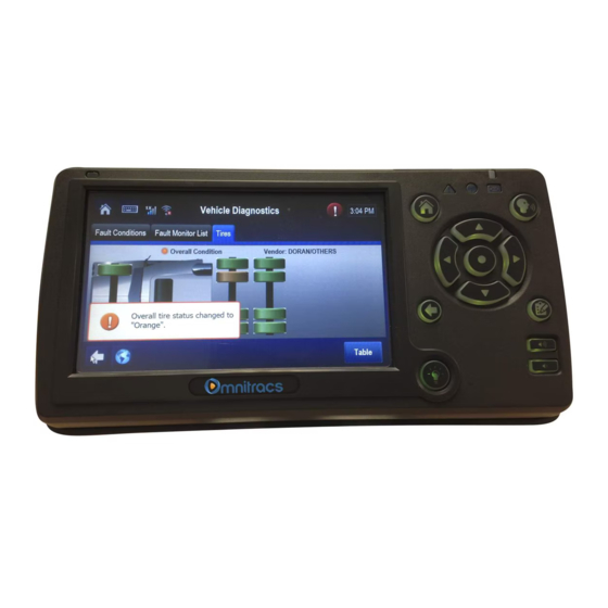
Page 165: Verify Configuration Settings
Vehicle Maintenance Verify Configuration Settings Verify Configuration Settings A customer selects which conditions to monitor using the Vehicle Maintenance host software. Select the Monitor List tab from the Vehicle Maintenance screens to see which are monitored. Verify Data Link Connections to Connect to J1939 Data Link Use the Display screens to verify vehicle maintenance: Go to the Vehicle Data Service (VDS) status screen. - Page 166 Verify Data Link Connections to Connect to J1939 Data Link Vehicle Maintenance With the ignition ON, verify the following on the VDS (Status) screen: • Ignition has a green indicator light during this test. • J1939 has a green indicator light. This confirms that the J1939 is enabled for the unit. The Rcv value should be constantly increasing.
- Page 167 Verify e-mail notification goes out upon detection of condition. The e-mail notification is sent to the person(s) identified by the host vehicle maintenance application. If the appropriate person does not receive e-mail notification, contact Omnitracs Customer Support at (800) 541-7490.
- Page 168 Verify Data Link Connections to Connect to J1939 Data Link Vehicle Maintenance 18-6 80-JB423-1 Rev. F MAY CONTAIN U.S. AND INTERNATIONAL EXPORT CONTROLLED INFORMATION...
- Page 169 ..........19-6 For technical questions, contact Omnitracs Customer Support. Customer Support is staffed 24 hours a day, 365 days a year: •...
-
Page 170: Normal Performance
Panic Button Diagnostic Procedures Normal Performance The panic button allows the driver to notify the MCP110 NOC and the company dispatcher when an emergency situation exists. When the driver presses the panic button, a priority message is sent to the NOC and the company dispatcher. -
Page 171: False Panic Message
False Panic Message Step 1 Remember: Disconnect Notify Omnitracs Customer Support that you are working accessory cable on the Panic Button both before and after you perform this procedure. connector Customer Support will then be aware of when an alarm is a test and when it is real. - Page 172 False Panic Message Panic Button Diagnostic Procedures Diagnostic Procedure The steps in this procedure match the steps on the flowchart on the previous page. The steps are not always sequential— you may be instructed to skip steps. Disconnect the accessory cable connector at the mobile application server 110 (MAS110).
- Page 173 • If yes, perform the system verification procedure in Chapter 4: System Verification. Notify Omnitracs Customer Support that you are finished with the test. • If no, notify Omnitracs Customer Support about the problem. 80-JB423-1 Rev. F 19-5 MAY CONTAIN U.S. AND INTERNATIONAL EXPORT CONTROLLED INFORMATION...
-
Page 174: No Panic Message
No Panic Message Panic Button Diagnostic Procedures No Panic Message Remember: Notify Omnitracs Customer Support that you are working Step 1 on the Panic Button both before and after you perform this procedure. Check the Customer Support will then be aware of when an alarm is a test and when it is real. - Page 175 From the Home screen, touch the System button. Touch the Config tab. Check that PANIC is enabled and Panic Config is 2-wire. Call Omnitracs Customer Support to let them know you will be testing the panic button. Press the panic button. Message should show in Outbox and a TTS notification will play.
- Page 176 No Panic Message Panic Button Diagnostic Procedures Repair or replace the panic button. Return to step 1. Panic Button Switch Disconnect the accessory cable from the Accessory Cable MAS110. With PANIC_LOW and Panic Button Input Wires: PANIC_HIGH still shorted together, check the resistance on the MAS110 end of the PANIC_HIGH accessory cable—pins 28 and 30.
- Page 177 • If the panic message was sent, the MAS110 is faulty. Replace the MAS110. Note Before sending a faulty MAS110 back to Omnitracs, remove the backup battery and install it in the replacement MAS110. A replacement MAS110 does not come with a backup battery.
- Page 178 No Panic Message Panic Button Diagnostic Procedures 19-10 80-JB423-1 Rev. F MAY CONTAIN U.S. AND INTERNATIONAL EXPORT CONTROLLED INFORMATION...
- Page 179 ........... 20-3 For technical questions, contact Omnitracs Customer Support. Customer Support is staffed 24 hours a day, 365 days a year: •...
-
Page 180: Overview
Overview In-Cab Scanner Diagnostic Procedures Overview The scanner is used to scan and send documents using the connected MCP110 system. The scanner is connected to the MAS using a USB cable. Normal Performance Once a document is scanned and accepted, the user can sends a scan of lading or other paperwork associated with pick-ups and deliveries. -
Page 181: Troubleshooting
In-Cab Scanner Diagnostic Procedures Troubleshooting Troubleshooting First, check the scanning application. It indicates whether or not the scanner is detected. If not detected, reseat the cable at both ends (scanner and MAS). Next, If the scanner is detected, run the calibration process and then try scanning a document again. - Page 182 Troubleshooting In-Cab Scanner Diagnostic Procedures 20-4 80-JB423-1 Rev. F MAY CONTAIN U.S. AND INTERNATIONAL EXPORT CONTROLLED INFORMATION...
-
Page 183: For Technical Questions, Contact Omnitracs Customer Support
Wiring Diagrams and Charts Topics in this appendix provide wiring diagrams and pin description charts for the Omnitracs MCP110 and accessories. Omnitracs MCP110 Electrical Diagram ........ -
Page 184: Omnitracs Mcp110 Electrical Diagram
Omnitracs MCP110 Electrical Diagram Wiring Diagrams and Charts Omnitracs MCP110 Electrical Diagram DIU110 WIB Antenna IO 1 IO 2 +9 VDC to +32 VDC MAS110 Vehicle Battery Power Cable 10 AMP Cable Chassis Cable 3 AMP Ignition Switch Can Converter Cable... -
Page 185: Omnitracs Mcp110 Wiring Diagram
Wiring Diagrams and Charts Omnitracs MCP110 Wiring Diagram Omnitracs MCP110 Wiring Diagram MCP Wiring Diagram CAN1 Connector Wireless Interface Box I/O Cable (WIB) Antenna WIB Cable IO 1 DIU Cable 0 I / Mobile Application Server (MAS110) Power Cable Power Cable... -
Page 186: Power Cable Connector Pin Callouts
Power Cable Connector Pin Callouts Wiring Diagrams and Charts Power Cable Connector Pin Callouts SIGNAL COLOR 8 (BAT RTN) BLACK 15 (BAT RTN) BLACK 14 (BAT RTN) BLACK 6 (ID) 5 (IGNITION) WHITE 3AMP Switched 12VDC Fuse 2 (BAT+) 12 VDC YELLOW 9 (BAT+) 12 VDC YELLOW... -
Page 187: Wireless Interface Box (Wib) Cable Connector Pin Callouts
Wiring Diagrams and Charts Wireless Interface Box (WIB) Cable Connector Pin Callouts Wireless Interface Box (WIB) Cable Connector Pin Callouts COLOR SIGNAL WIB _TEMPER_1 Black WIB _TEMPER_2 Gray WIB _Gnd WIB_9 V Blue Green WIB _Gnd Violet WIB _DATA_P Yellow WIB _DATA_M Orange USB_VCC... -
Page 188: Speaker Switch Cable
Speaker Switch Cable Wiring Diagrams and Charts Speaker Switch Cable 80-JB423-1 Rev. F MAY CONTAIN U.S. AND INTERNATIONAL EXPORT CONTROLLED INFORMATION... - Page 189 Wiring Diagrams and Charts Primary Accessory Cable Connector Pin Callouts Primary Accessory Cable Connector Pin Callouts COLOR SIGNAL (CAN1_HI) (CAN1_HI) 19 19 WHT/BLU 20 WHT/BLU 20 BRN/WHT 22 BRN/WHT 22 (CAN_GND (CAN_GND 18 18 WHT/BRN 22 WHT/BRN 22 (CAN_PWR (CAN_PWR (CAN1_LO) (CAN1_LO) BLU/WHT 20...
-
Page 190: Mcp100 To Mcp200 Accessory Adapter Cable
MCP100 to MCP200 Accessory Adapter Cable Wiring Diagrams and Charts MCP100 to MCP200 Accessory Adapter Cable 80-JB423-1 Rev. F MAY CONTAIN U.S. AND INTERNATIONAL EXPORT CONTROLLED INFORMATION... -
Page 191: Display Interface Unit 110 (Diu110) Cable Connector Pin Callouts
Wiring Diagrams and Charts Display Interface Unit 110 (DIU110) Cable Connector Pin Callouts Display Interface Unit 110 (DIU110) Cable Connector Pin Callouts COLOR SIGNAL (LVDS+) (LVDS+) (LVDS+) (LVDS-) (LVDS-) (LVDS-) Black Gray (GND) (GND) (GND) Violet (GND) (GND) (GND) (V+) (V+) (V+) DIU PORT... -
Page 192: Six-Pin Data Link Connector Pin Callouts
Six-pin Data Link Connector Pin Callouts Wiring Diagrams and Charts Six-pin Data Link Connector Pin Callouts 08AAA_050 SIGNAL J1708/J1587 DATA LINK+ J1708/J1587 DATA LINK- +12VDC PLUG P/N:23507136 BATTERY GROUND PLUG P/N:23507136 A-10 80-JB423-1 Rev. F MAY CONTAIN U.S. AND INTERNATIONAL EXPORT CONTROLLED INFORMATION... -
Page 193: Nine-Pin Data Link Connector Pin Callouts
Wiring Diagrams and Charts Nine-pin Data Link Connector Pin Callouts Nine-pin Data Link Connector Pin Callouts 08AAA_051 SIGNAL BATTERY GROUND +12VDC J1939 DATA LINK+ J1939 DATA LINK- J1939 SHIELD J1708/J1587 DATA LINK+ J1708/J1587 DATA LINK- PLUG PLUG 80-JB423-1 Rev. F A-11 MAY CONTAIN U.S. -
Page 194: Radio Connector Pin Callouts
Radio Connector Pin Callouts Wiring Diagrams and Charts Radio Connector Pin Callouts Common Radio and Harness Front Drivers Side Speaker Wire (B5) Notches Note: Connector tabs on this side Front Drivers Side Speaker Wire (B6) SIGNAL SIGNAL RR + SPEAKER RR - SPEAKER PARK LIGHTS RF + SPEAKER... -
Page 195: Can Repeater Cable Pin Callouts
Wiring Diagrams and Charts CAN Repeater Cable Pin Callouts CAN Repeater Cable Pin Callouts J1939 CAN REPEATER-R J1939 CAN REPEATER-R J1939 CAN REPEATER-R J1939 CAN REPEATER-R J1939 CAN REPEATER-R (CAN1_HI ) Yellow Yellow Green Green (CAN1_LO) 09AAA_043 80-JB423-1 Rev. F A-13 MAY CONTAIN U.S. -
Page 196: Can Repeater Cable Pin Callouts
CAN Repeater Cable Pin Callouts Wiring Diagrams and Charts A-14 80-JB423-1 Rev. F MAY CONTAIN U.S. AND INTERNATIONAL EXPORT CONTROLLED INFORMATION... -
Page 197: Appendix B Environmental And Power Requirements
Environmental and Power Requirements Topics in this appendix provide environmental and power requirements for the Omnitracs MCP110 and accessories. MCP110 Environmental and Power Requirements ...... -
Page 198: Mcp110 Environmental And Power Requirements
Not watertight. Turn over immediately if liquids are spilled on it. Power +12 to +32 Volts DC Operating at +12V (WIB and DIU) MCP110 draws a maximum of 1.5 amps. Asleep MCP110 draws 30mA. 80-JB423-1 Rev. F MAY CONTAIN U.S. AND INTERNATIONAL EXPORT CONTROLLED INFORMATION... -
Page 199: Appendix C Standard Rma Procedure
For customers, to return failed equipment, go to Omnitracs Customer Portal at https://customer.omnitracs.com For service centers only, please return equipment to Omnitracs at the following address. Make sure that the RMA number is marked clearly on the outside of the box. - Page 200 Standard RMA Procedure 80-JB423-1 Rev. F MAY CONTAIN U.S. AND INTERNATIONAL EXPORT CONTROLLED INFORMATION...
-
Page 201: Appendix D Upgrading The Mcp110 Using Usb Memory Sticks
Upgrading the MCP110 Using USB Memory Sticks An MCP110 is normally upgraded with software by sending it over-the-air using satellite connectivity. However, there may be occasions when upgrades are necessary using USB memory sticks. Topics in this appendix include: Checking the Software Versions Installed . -
Page 202: Checking The Software Versions Installed
Upgrading the MCP110 Using USB Memory Sticks Checking the Software Versions Installed Shortly after you power up the MCP110, the user interface screen displays. Use the left arrow to get to the System button. Tap the System button. Tap the System tab. Tap the Version button at the bottom right to access system information about the MCP110. -
Page 203: Upgrading Only The Mas110 Software
Upgrading the MCP110 Using USB Memory Sticks Upgrading Only the MAS110 Software Upgrading Only the MAS110 Software MAS110 should be powered ON, ignition ON. Insert the MAS110 software memory stick into one of the USB ports on the MAS or into the memory stick slot on the side of the DIU. -
Page 204: Upgrading The Mas Os And Mas Software
Do NOT disrupt power or remove the USB stick during the upgrade process as this will cause the unit to be inoperable. The entire process takes about 1 hour to complete. Starting with an MCP110 system that has had power removed – no MAS LEDs on, do the following: 80-JB423-1 Rev. - Page 205 Upgrading the MCP110 Using USB Memory Sticks Upgrading the MAS OS and MAS Software Put the USB memory stick in a UBS port on the MAS. This process will NOT work using the DIU USB port. USB Stick A USB keyboard will need to be attached to a USB port on the DIU or MAS. Be ready to press the F11 key.
- Page 206 Upgrading the MAS OS and MAS Software Upgrading the MCP110 Using USB Memory Sticks Within a minute the unit will start the OS upgrade. The screens below will be displayed. The OS upgrade will automatically start. At about 30 minutes, the system will reboot after the OS components are copied and verified.
- Page 207 Upgrading the MCP110 Using USB Memory Sticks Upgrading the MAS OS and MAS Software At the System Check screen, press the Install Application button. This will start the software application installation. When the application software installation is complete, the screen will show a Driver Warning (takes about 15 minutes).
- Page 208 Upgrading the MAS OS and MAS Software Upgrading the MCP110 Using USB Memory Sticks 80-JB423-1 Rev. F MAY CONTAIN U.S. AND INTERNATIONAL EXPORT CONTROLLED INFORMATION...
-
Page 209: Glossary
Calibration. Calibration is performed when the MCP110 cannot use the J1708/1587 data link for Performance Monitoring input. After sensor calibrations have been determined, the dispatch computer operator needs to send the calibration numbers to the MCP110. See RPM Calibration and Speed/Distance Calibration. - Page 210 J1708 Enabled. “J1708 enabled” means that the MCP110 has been set up to look at J1708 data via the J1708/1587 data link. The dispatch computer operator must send a message to the MCP110 that “tells” it to understand input from the J1708/1587 bus and define driving thresholds.
- Page 211 NMC. See Network Management Computer. NOC. See Network Operations Center. NO SIGNAL Light. An indicator light on the display that comes on if the MCP110 has lost contact with the data satellite and is searching for the satellite signal. Odometer Screen. The MCP110 display unit screen that displays the life-to-date (LTD) value and sensor calibration information.
- Page 212 Printer, Scanner, Axle, RPM, and PTOP/PTOC. See Appendix A for details on pinouts. Printer. Provides the driver with a hard copy of the MCP110 forward or return message screen display. Received Signal Strength Indication (RSSI). The strength of the wireless network signal being received by the antenna during forward link acquisition to the wireless network provider.
- Page 213 The dispatch computer operator must send a message to the MCP110 that “tells” it to understand input from the traditional sensors and define speed and RPM.
- Page 214 80-JB423-1 Rev. F MAY CONTAIN U.S. AND INTERNATIONAL EXPORT CONTROLLED INFORMATION...
Need help?
Do you have a question about the MCP110 and is the answer not in the manual?
Questions and answers