Sign In
Upload
Manuals
Brands
NXP Semiconductors Manuals
Controller
PCA9665
NXP Semiconductors PCA9665 Manuals
Manuals and User Guides for NXP Semiconductors PCA9665. We have
1
NXP Semiconductors PCA9665 manual available for free PDF download: Product Data Sheet
NXP Semiconductors PCA9665 Product Data Sheet (91 pages)
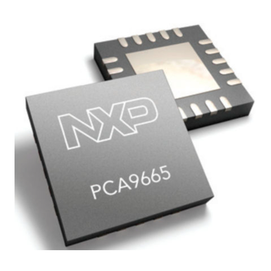
Fm+ parallel bus to I2C-bus controller
Brand:
NXP Semiconductors
| Category:
Controller
| Size: 0 MB
Table of Contents
1 General Description
1
2 Features
1
3 Applications
2
4 Ordering Information
2
C-Bus Controller
2
5 Block Diagram
3
6 Pinning Information
4
Pinning
4
Pin Description
5
7 Functional Description
6
General
6
Internal Oscillator
6
Registers
6
Direct Registers
8
The Status Register, I2CSTA (A1 = 0, A0 = 0)
8
The Indirect Pointer Register, INDPTR (A1 = 0, A0 = 0)
8
The I C-Bus Data Register, I2CDAT
8
The Control Register, I2CCON (A1 = 1, A0 = 1)
9
Reset
10
The Indirect Data Field Access Register, INDIRECT (A1 = 1, A0 = 0)
11
Indirect Registers
12
The Byte Count Register, I2CCOUNT (Indirect Address 00H)
12
The Own Address Register, I2CADR (Indirect Address 01H)
12
The Clock Rate Registers, I2CSCLL and I2CSCLH (Indirect Addresses 02H and 03H)
13
The Time-Out Register, I2CTO (Indirect Address 04H)
14
The Parallel Software Reset Register, I2CPRESET (Indirect Address 05H)
14
The I C-Bus Mode Register, I2CMODE (Indirect Address 06H)
15
8 PCA9665 Modes
16
Configuration Modes
16
Byte Mode
16
Buffered Mode
16
Operating Modes
16
Byte Mode
17
Master Transmitter Byte Mode
17
Master Receiver Byte Mode
22
Slave Receiver Byte Mode
25
Slave Transmitter Byte Mode
29
Buffered Mode
31
Master Transmitter Buffered Mode
31
Master Receiver Buffered Mode
36
Slave Receiver Buffered Mode
40
Slave Transmitter Buffered Mode
45
Buffered Mode Examples
48
Buffered Master Transmitter Mode of Operation
48
Buffered Master Receiver Mode of Operation
48
Buffered Slave Transmitter Mode
49
Buffered Slave Receiver Mode
50
Location 08H
50
I2CCOUNT Register
51
Acknowledge Management
53
Buffered Modes
53
Miscellaneous States
57
I2CSTA = F8H
57
I2CSTA = 00H
57
I2CSTA = 70H
57
I2CSTA = 78H
58
Some Special Cases
58
Simultaneous Repeated START Conditions from Two Masters
58
Data Transfer after Loss of Arbitration
58
Forced Access to the I C-Bus
58
I 2 C-Bus Obstructed by a LOW Level on SCL or SDA
59
Bus Error
60
Power-On Reset
60
Reset
61
I C-Bus Timing Diagrams, Unbuffered Mode
61
I C-Bus Timing Diagrams, Buffered Mode
63
9 Characteristics of the I C-Bus
65
Bit Transfer
65
START and STOP Conditions
65
System Configuration
65
Acknowledge
66
10 Application Design-In Information
67
SpecifiC Applications
67
Add I C-Bus Port
67
Add Additional I C-Bus Ports
68
Convert 8 Bits of Parallel Data into
68
I 2 C-Bus Serial Data Stream
68
11 Limiting Values
69
12 Static Characteristics
70
13 Dynamic Characteristics
71
14 Test Information
78
15 Package Outline
79
16 Handling Information
83
17 Soldering
83
Introduction
83
Through-Hole Mount Packages
83
Soldering by Dipping or by Solder Wave
83
Manual Soldering
83
Surface Mount Packages
83
Reflow Soldering
83
Wave Soldering
85
Manual Soldering
85
Package Related Soldering Information
85
18 Abbreviations
87
19 Revision History
87
20 Legal Information
89
Data Sheet Status
89
Definitions
89
Disclaimers
89
Trademarks
89
21 Contact Information
89
Pinning Information
90
22 Contents
90
Advertisement
Advertisement
Related Products
NXP Semiconductors PXN2020
NXP Semiconductors PXN2120
NXP Semiconductors PN7150
NXP Semiconductors PN7150X
NXP Semiconductors PT2001
NXP Semiconductors PN7120S
NXP Semiconductors PN5331B3HN
NXP Semiconductors PN5331B3HN/C270
NXP Semiconductors PN5331B3HN/C270,55
NXP Semiconductors PN7120
NXP Semiconductors Categories
Motherboard
Microcontrollers
Computer Hardware
Control Unit
Controller
More NXP Semiconductors Manuals
Login
Sign In
OR
Sign in with Facebook
Sign in with Google
Upload manual
Upload from disk
Upload from URL