Sign In
Upload
Manuals
Brands
NXP Semiconductors Manuals
Microcontrollers
Kinetis KE1xZ256
NXP Semiconductors Kinetis KE1xZ256 MCUs Manuals
Manuals and User Guides for NXP Semiconductors Kinetis KE1xZ256 MCUs. We have
1
NXP Semiconductors Kinetis KE1xZ256 MCUs manual available for free PDF download: Reference Manual
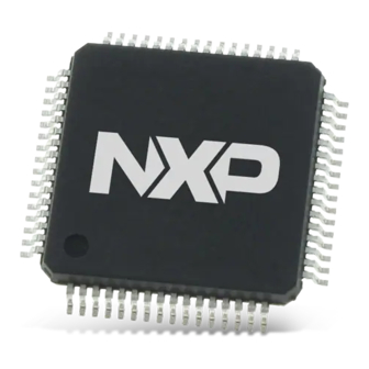
NXP Semiconductors Kinetis KE1xZ256 Reference Manual (1325 pages)
Brand:
NXP Semiconductors
| Category:
Microcontrollers
| Size: 12 MB
Table of Contents
Table of Contents
3
Chapter 1 About this Manual
43
Audience
43
Organization
43
Module Descriptions
43
Example: Chip-Specific Information that Supersedes Content in the same Chapter
44
Example: Chip-Specific Information that Refers to a Different Chapter
45
Register Descriptions
46
Conventions
47
Numbering Systems
47
Typographic Notation
47
Special Terms
48
Chapter 2 Introduction
49
Overview
49
Block Diagram
49
Module Functional Categories
50
Chapter 3 Core Overview
53
ARM Cortex-M0
53
Core Buses and Interfaces
54
Core Component Configuration
55
Systick Clock Configuration
55
Chapter 4 Interrupts
57
Introduction
57
NVIC Configuration
57
Interrupt Priority Levels
57
Non-Maskable Interrupt
58
Interrupt Channel Assignments
58
Determining the Bitfield and Register Location for Configuring a Particular Interrupt
60
Chapter 5 System Integration Module (SIM)
63
Introduction
63
Features
63
Memory Map and Register Definition
63
Chip Control Register (SIM_CHIPCTL)
64
FTM Option Register 0 (SIM_FTMOPT0)
66
ADC Options Register (SIM_ADCOPT)
67
FTM Option Register 1 (SIM_FTMOPT1)
69
System Device Identification Register (SIM_SDID)
71
Flash Configuration Register 1 (SIM_FCFG1)
72
Flash Configuration Register 2 (SIM_FCFG2)
74
Unique Identification Register High (SIM_UIDH)
75
Unique Identification Register MID-High (SIM_UIDMH)
75
Unique Identification Register MID Low (SIM_UIDML)
76
Unique Identification Register Low (SIM_UIDL)
76
Miscellaneous Control Register (SIM_MISCTRL)
77
Chapter 6 Memory-Mapped Divide and Square Root (MMDVSQ)
79
Chip-Specific Information for this Module
79
Introduction
79
Features
79
Block Diagram
80
Modes of Operation
82
External Signal Description
83
Memory Map and Register Definition
83
Dividend Register (MMDVSQ_DEND)
84
Divisor Register (MMDVSQ_DSOR)
84
Control/Status Register (MMDVSQ_CSR)
86
Result Register (MMDVSQ_RES)
89
Radicand Register (MMDVSQ_RCND)
89
Functional Description
90
Algorithms
90
Execution Times
93
Software Interface
95
Chapter 7 Miscellaneous Control Module (MCM)
97
Chip-Specific Information for this Module
97
Introduction
98
Features
98
Memory Map/Register Descriptions
98
Crossbar Switch (AXBS) Slave Configuration (MCM_PLASC)
99
Crossbar Switch (AXBS) Master Configuration (MCM_PLAMC)
99
Platform Control Register (MCM_PLACR)
100
Compute Operation Control Register (MCM_CPO)
103
Chapter 8 Bit Manipulation Engine (BME)
105
Chip-Specific Information for this Module
105
Introduction
105
Overview
106
Features
107
Modes of Operation
107
Memory Map and Register Definition
107
Functional Description
108
BME Decorated Stores
108
BME Decorated Loads
115
Additional Details on Decorated Addresses and GPIO Accesses
121
Application Information
122
Chapter 9 Crossbar Switch Lite (AXBS-Lite)
125
Chip-Specific Information for this Module
125
Introduction
126
Features
126
Memory Map / Register Definition
127
Functional Description
127
General Operation
127
Arbitration
128
Initialization/Application Information
129
Chapter 10 Peripheral Bridge (AIPS-Lite)
131
Chip-Specific Information for this Module
131
Instantiation Information
131
Introduction
132
Features
133
General Operation
133
Memory Map/Register Definition
133
Functional Description
133
Access Support
133
Chapter 11 Trigger MUX Control (TRGMUX)
135
Chip-Specific Information for this Module
135
Module Interconnectivity
135
Introduction
140
Features
140
Functional Description
140
Memory Map and Register Definition
140
TRGMUX1 Register Descriptions
140
TRGMUX0 Register Descriptions
145
Usage Guide
176
ADC Trigger Source
176
CMP Window/Sample Input
177
FTM Fault Detection Input / Hardware Triggers and Synchronization
177
Chapter 12 Direct Memory Access Multiplexer (DMAMUX)
179
Chip-Specific Information for this Module
179
DMAMUX Request Sources
179
DMA Trigger Sources
181
Introduction
181
Overview
182
Features
182
Modes of Operation
183
External Signal Description
183
Memory Map/Register Definition
183
Channel Configuration Register (Dmamux_Chcfgn)
184
Functional Description
185
DMA Channels with Periodic Triggering Capability
185
DMA Channels with no Triggering Capability
187
Always-Enabled DMA Sources
188
Initialization/Application Information
189
Reset
189
Enabling and Configuring Sources
189
Chapter 13 Enhanced Direct Memory Access (Edma)
193
Introduction
193
Edma System Block Diagram
193
Block Parts
194
Features
195
Modes of Operation
196
Memory Map/Register Definition
197
TCD Memory
197
TCD Initialization
197
TCD Structure
198
Reserved Memory and Bit Fields
198
Control Register (DMA_CR)
204
Error Status Register (DMA_ES)
207
Enable Request Register (DMA_ERQ)
209
Enable Error Interrupt Register (DMA_EEI)
211
Clear Enable Error Interrupt Register (DMA_CEEI)
212
Set Enable Error Interrupt Register (DMA_SEEI)
213
Clear Enable Request Register (DMA_CERQ)
214
Set Enable Request Register (DMA_SERQ)
215
Clear DONE Status Bit Register (DMA_CDNE)
216
Set START Bit Register (DMA_SSRT)
217
Clear Error Register (DMA_CERR)
218
Clear Interrupt Request Register (DMA_CINT)
219
Interrupt Request Register (DMA_INT)
220
Error Register (DMA_ERR)
221
Hardware Request Status Register (DMA_HRS)
223
Enable Asynchronous Request in Stop Register (DMA_EARS)
225
Channel N Priority Register (Dma_Dchprin)
226
TCD Source Address (Dma_Tcdn_Saddr)
227
TCD Signed Source Address Offset (Dma_Tcdn_Soff)
227
TCD Transfer Attributes (Dma_Tcdn_Attr)
228
TCD Minor Byte Count (Minor Loop Mapping Disabled) (Dma_Tcdn_Nbytes_Mlno)
229
TCD Signed Minor Loop Offset (Minor Loop Mapping Enabled and Offset Disabled)
229
(Dma_Tcdn_Nbytes_Mloffno)
229
TCD Signed Minor Loop Offset (Minor Loop Mapping and Offset Enabled)
231
(Dma_Tcdn_Nbytes_Mloffyes)
231
TCD Last Source Address Adjustment (Dma_Tcdn_Slast)
232
TCD Destination Address (Dma_Tcdn_Daddr)
232
TCD Signed Destination Address Offset (Dma_Tcdn_Doff)
233
(Dma_Tcdn_Citer_Elinkyes)
233
(Dma_Tcdn_Citer_Elinkno)
235
TCD Current Minor Loop Link, Major Loop Count (Channel Linking Disabled Dma_Tcdn_Citer_Elinkno)
235
TCD Last Destination Address Adjustment/Scatter Gather Address (Dma_Tcdn_Dlastsga)
236
TCD Control and Status (Dma_Tcdn_Csr)
236
TCD Beginning Minor Loop Link, Major Loop Count (Channel Linking Enabled)
239
(Dma_Tcdn_Biter_Elinkyes)
239
TCD Beginning Minor Loop Link, Major Loop Count (Channel Linking Disabled)
240
(Dma_Tcdn_Biter_Elinkno)
240
Functional Description
241
Edma Basic Data Flow
241
Fault Reporting and Handling
244
Channel Preemption
246
Performance
247
Initialization/Application Information
251
Edma Initialization
251
Programming Errors
253
Arbitration Mode Considerations
253
Performing DMA Transfers
254
Monitoring Transfer Descriptor Status
258
Channel Linking
260
Dynamic Programming
261
Suspend/Resume a DMA Channel with Active Hardware Service Requests
265
Usage Guide
266
Chapter 14 Memory and Memory Map
267
Introduction
267
Flash Memory
269
Flash Memory Types
269
Flash Memory Sizes
269
SRAM Memory
270
SRAM Sizes
270
SRAM Retention in Low Power Modes
270
System Memory Map
270
Aliased Bit-Band Regions
272
Bit Manipulation Engine
273
Peripheral Memory Map
273
Peripheral Bridge (AIPS-Lite) Memory Map
274
Private Peripheral Bus (PPB) Memory Map
277
Chapter 15 Flash Acceleration Unit (FAU)
279
Introduction
279
Modes of Operation
279
External Signal Description
279
Memory Map and Register Descriptions
280
Functional Description
280
Usage Guide
280
FAU Features
281
FAU Configuration
281
Chapter 16 Flash Memory Module (FTFE)
283
Chip-Specific Information for this Module
283
Introduction
283
Features
284
Block Diagram
286
Glossary
286
External Signal Description
288
Memory Map and Registers
289
Flash Configuration Field Description
289
Program Flash 0 IFR Map
289
Data Flash 0 IFR Map
290
Register Descriptions
293
Functional Description
309
Flash Protection
309
Flash Access Protection
311
Flexnvm Description
312
Interrupts
316
Flash Operation in Low-Power Modes
317
Flash Memory Reads and Ignored Writes
317
Read While Write (RWW)
317
Flash Program and Erase
318
FTFE Command Operations
318
Margin Read Commands
325
Flash Command Descriptions
326
Security
351
Security
352
Reset Sequence
354
Usage Guide
355
Clock Distribution
357
Introduction
357
High-Level Clocking Diagram
358
Clock Definitions
358
Typical Clock Configuration
359
Default Start-Up Clock
359
VLPR Mode Clocking
360
Clock Gating
360
Module Clocks
360
LPO Clock Distribution
362
EWM Clocks
362
WDOG Clocking Information
362
ADC Clocking Information
363
WDOG Clocking Information
363
PDB Clock Options
364
FTM Clocking Information
364
LPTMR Prescaler/Glitch Filter Clocking Options
365
RTC Clocking Information
365
TSI Clocking Information
366
Module Clocking Information for LPUART, LPSPI, LPI2C, Flexio and LPIT
367
Chapter 18 System Clock Generator (SCG)
369
Chip-Specific Information for this Module
369
Instantiation Information
369
Introduction
372
Features
372
Memory Map/Register Definition
373
Version ID Register (SCG_VERID)
374
Parameter Register (SCG_PARAM)
374
Clock Status Register (SCG_CSR)
375
Run Clock Control Register (SCG_RCCR)
377
VLPR Clock Control Register (SCG_VCCR)
379
SCG CLKOUT Configuration Register (SCG_CLKOUTCNFG)
381
System OSC Control Status Register (SCG_SOSCCSR)
382
System OSC Divide Register (SCG_SOSCDIV)
384
System Oscillator Configuration Register (SCG_SOSCCFG)
385
Slow IRC Control Status Register (SCG_SIRCCSR)
387
Slow IRC Divide Register (SCG_SIRCDIV)
388
Slow IRC Configuration Register (SCG_SIRCCFG)
389
Fast IRC Control Status Register (SCG_FIRCCSR)
390
Fast IRC Divide Register (SCG_FIRCDIV)
392
Fast IRC Configuration Register (SCG_FIRCCFG)
393
Fast IRC Trim Configuration Register (SCG_FIRCTCFG)
394
Fast IRC Status Register (SCG_FIRCSTAT)
395
Low Power FLL Control Status Register (SCG_LPFLLCSR)
396
Low Power FLL Divide Register (SCG_LPFLLDIV)
398
Low Power FLL Configuration Register (SCG_LPFLLCFG)
399
Low Power FLL Trim Configuration Register (SCG_LPFLLTCFG)
400
Low Power FLL Status Register (SCG_LPFLLSTAT)
401
Functional Description
402
SCG Clock Mode Transitions
402
Chapter 19 RTC Oscillator (OSC32)
405
Introduction
405
Features and Modes
405
Block Diagram
405
RTC Signal Descriptions
406
EXTAL32 - Oscillator Input
406
XTAL32 - Oscillator Output
406
External Crystal Connections
407
Memory Map/Register Descriptions
407
RTC Oscillator Control Register (OSC32_CR)
407
Functional Description
408
Reset Overview
409
Interrupts
409
Chapter 20 Peripheral Clock Controller (PCC)
411
Chip-Specific Information for this Module
411
Information of PCC on this Device
411
Introduction
411
Features
411
Functional Description
412
Memory Map and Register Definition
413
PCC Register Descriptions
413
Chapter 21 Reset and Boot
459
Introduction
459
Reset
460
Power-On Reset (POR)
460
System Resets
460
MCU Resets
463
Reset Pin
464
Boot
464
Boot Options
465
Boot Sequence
467
Chapter 22 Kinetis ROM Bootloader
469
Chip-Specific Information for this Module
469
Boot ROM Configuration
469
Introduction
470
Functional Description
471
The Kinetis Bootloader Configuration Area (BCA)
472
Start-Up Process
474
Clock Configuration
476
Bootloader Entry Point / API Tree
477
Bootloader Protocol
478
Bootloader Packet Types
481
Bootloader Command API
487
Bootloader Exit State
500
Flash Driver API Tree
501
Quick Demo Using Kinetis Flash Driver API
502
Flash Driver Data Structures
503
Flash Driver API
504
Peripherals Supported
518
SPI Peripheral
520
UART Peripheral
523
Get/Setproperty Command Properties
525
Property Definitions
527
Kinetis Bootloader Status Error Codes
528
Chip-Specific Information for this Module
531
Reset Memory Map and Register Descriptions
532
Parameter Register (RCM_PARAM)
534
System Reset Status Register (RCM_SRS)
536
Reset Pin Control Register (RCM_RPC)
539
Mode Register (RCM_MR)
540
Force Mode Register (RCM_FM)
541
Sticky System Reset Status Register (RCM_SSRS)
542
System Reset Interrupt Enable Register (RCM_SRIE)
544
Introduction
547
Power Modes Description
548
Chapter 24
549
Run Mode
549
Wait Mode
550
Stop Mode
551
Power Domains
553
Entering and Exiting Power Modes
554
Power Modes Shutdown Sequencing
555
Module Operation in Low Power Modes
556
Peripheral Doze
559
Low-Power Wake-Up Sources
560
Introduction
563
Memory Map and Register Descriptions
565
SMC Parameter Register (SMC_PARAM)
566
Power Mode Protection Register (SMC_PMPROT)
567
Power Mode Control Register (SMC_PMCTRL)
569
Stop Control Register (SMC_STOPCTRL)
570
Power Mode Status Register (SMC_PMSTAT)
572
Power Mode Transitions
573
Power Mode Entry/Exit Sequencing
574
Run Modes
576
Wait Modes
578
Stop Modes
579
Debug in Low Power Modes
580
Chip-Specific Information for this Module
581
Chapter 26
582
Full Performance Mode (FPM)
582
LVD Interrupt Operation
583
Low Voltage Detect Status and Control 1 Register (PMC_LVDSC1)
584
Low Voltage Detect Status and Control 2 Register (PMC_LVDSC2)
585
Regulator Status and Control Register (PMC_REGSC)
586
Low Power Oscillator Trim Register (PMC_LPOTRIM)
587
Introduction
589
Flash Access Protection (FAC)
590
Chapter 27
591
General Security Features
591
Introduction
593
Modes of Operation
594
Block Diagram
595
Chapter 28 EWM Signal Descriptions
596
Service Register (EWM_SERV)
597
Compare High Register (EWM_CMPH)
598
Clock Prescaler Register (EWM_CLKPRESCALER)
599
The Ewm_In Signal
600
EWM Counter
601
EWM Interrupt
602
Ewm_Out Pin State in Low Power Modes
603
Chip-Specific Information for this Module
605
Introduction
606
Block Diagram
607
Chapter 29
608
Watchdog Control and Status Register (WDOG_CS)
608
Watchdog Counter Register (WDOG_CNT)
611
Watchdog Window Register (WDOG_WIN)
612
Functional Description
613
Watchdog Refresh Mechanism
614
Configuring the Watchdog
616
Using Interrupts to Delay Resets
617
Functionality in Debug and Low-Power Modes
618
Application Information
619
Disable Watchdog
620
Refreshing the Watchdog
621
Introduction
623
Modes of Operation
624
Chapter 30
625
CRC Data Register (CRC_DATA)
625
CRC Polynomial Register (CRC_GPOLY)
626
Functional Description
627
CRC Initialization/Reinitialization
628
Transpose Feature
629
CRC Result Complement
631
Bit POSIX CRC
632
Bit KERMIT CRC
633
Introduction
635
Chapter 31
637
MDM-AP Status Register
637
MDM-AP Control Register
638
Debug Resets
639
Debug in Low-Power Modes
640
Introduction
641
Features
644
Modes of Operation
645
Memory Map and Register Definition
646
Chapter 32
658
MTB_DWT Memory Map
658
System ROM Memory Map
668
Usage Guide
672
ARM Reference
673
Introduction
675
Chapter 33
679
Pin Properties
679
Pinout Diagram
682
Module Signal Description Tables
684
Core Modules
685
Analog
686
Chip-Specific Information for this Module
691
Chapter 34
692
Port Control and Interrupt Module Features
692
Application-Related Information
693
Modes of Operation
694
External Signal Description
695
Pin Control Register N (Portx_Pcrn)
702
Global Pin Control Low Register (Portx_Gpclr)
705
Interrupt Status Flag Register (Portx_Isfr)
706
Digital Filter Clock Register (Portx_Dfcr)
707
Functional Description
708
Global Pin Control
709
Digital Filter
710
Chip-Specific Information for this Module
713
Features
714
Memory Map and Register Definition
715
Port Data Output Register (Gpiox_Pdor)
717
Port Set Output Register (Gpiox_Psor)
718
Port Toggle Output Register (Gpiox_Ptor)
719
Port Data Direction Register (Gpiox_Pddr)
720
Port Data Output Register (Fgpiox_Pdor)
722
Port Clear Output Register (Fgpiox_Pcor)
723
Port Data Input Register (Fgpiox_Pdir)
724
Functional Description
725
Ioport
726
Chip-Specific Information for this Module
727
ADC Clocking Information
730
Application-Related Information
731
Introduction
736
Block Diagram
737
ADC Signal Descriptions
738
Voltage Reference Select
739
Analog Channel Inputs (Adx)
740
ADC Status and Control Register 1 (Adcx_Sc1N)
742
ADC Configuration Register 1 (Adcx_Cfg1)
745
ADC Configuration Register 2 (Adcx_Cfg2)
746
ADC Data Result Registers (Adcx_Rn)
747
Compare Value Registers (Adcx_Cvn)
748
Status and Control Register 2 (Adcx_Sc2)
749
Status and Control Register 3 (Adcx_Sc3)
751
BASE Offset Register (Adcx_Base_Ofs)
752
USER Offset Correction Register (Adcx_Usr_Ofs)
753
ADC X Offset Correction Register (Adcx_Xofs)
754
ADC User Gain Register (Adcx_Ug)
755
ADC Plus-Side General Calibration Value Register 3 (Adcx_Clp3)
756
ADC Plus-Side General Calibration Value Register 2 (Adcx_Clp2)
757
ADC Plus-Side General Calibration Value Register 0 (Adcx_Clp0)
758
ADC Plus-Side General Calibration Value Register 9 (Adcx_Clp9)
759
ADC General Calibration Offset Value Register S (Adcx_Clps_Ofs)
760
ADC Plus-Side General Calibration Offset Value Register 2 (Adcx_Clp2_Ofs)
761
ADC Plus-Side General Calibration Offset Value Register X (Adcx_Clpx_Ofs)
762
Functional Description
763
Voltage Reference Selection
764
Conversion Control
765
Automatic Compare Function
769
Calibration Function
770
User-Defined Offset Function
771
MCU Wait Mode Operation
772
MCU Normal Stop Mode Operation
773
Pseudo-Code Example
774
Calibration
775
Application Hints
776
ADC Trigger Concept – Use Case
777
ADC Self-Test and Calibration Scheme
778
Chip-Specific Information for this Module
779
Chapter 37
780
CMP Clocking Information
780
Inter-Connectivity Information
781
Application-Related Information
782
Introduction
784
Bit DAC Key Features
785
CMP, DAC, and ANMUX Diagram
786
CMP Block Diagram
787
CMP Pin Descriptions
788
External Pins
789
Disabled Mode (# 1)
791
Sampled, Non-Filtered Mode (#S 3A & 3B)
792
Sampled, Filtered Mode (#S 4A & 4B)
793
Windowed Mode (#S 5A & 5B)
795
Windowed/Filtered Mode (#7)
798
Memory Map/Register Definitions
799
CMP Control Register 1 (Cmpx_C1)
803
CMP Control Register 2 (Cmpx_C2)
806
CMP Functional Description
808
Initialization
809
Interrupts
811
DMA Support
812
DAC Resets
813
Usage Guide
816
Window Mode
817
Chip-Specific Information for this Module
821
Inter-Connectivity Information
822
Introduction
824
Chapter 38
825
Implementation
825
Block Diagram
826
Modes of Operation
827
Status and Control Register (Pdbx_Sc)
829
Modulus Register (Pdbx_Mod)
832
Interrupt Delay Register (Pdbx_Idly)
833
Channel N Status Register (Pdbx_Chns)
834
Channel N Delay 0 Register (Pdbx_Chndly0)
835
Channel N Delay 1 Register (Pdbx_Chndly1)
836
Pulse-Out N Delay Register (Pdbx_Pondly)
837
PDB Trigger Input Source Selection
840
Updating the Delay Registers
841
Interrupts
843
Impact of Using the Prescaler and Multiplication Factor on Timing Resolution
844
Chip-Specific Information for this Module
845
Chapter 48 Inter-Connectivity Information
846
Introduction
850
Features
851
Modes of Operation
853
FTM Signal Descriptions
855
Register Descriptions
856
Status and Control (Ftmx_Sc)
862
Counter (Ftmx_Cnt)
865
Channel (N) Status and Control (Ftmx_Cnsc)
867
Channel (N) Value (Ftmx_Cnv)
869
Capture and Compare Status (Ftmx_Status)
870
Features Mode Selection (Ftmx_Mode)
872
Synchronization (Ftmx_Sync)
874
Initial State for Channels Output (Ftmx_Outinit)
876
Output Mask (Ftmx_Outmask)
878
Function for Linked Channels (Ftmx_Combine)
880
Deadtime Configuration (Ftmx_Deadtime)
884
FTM External Trigger (Ftmx_Exttrig)
885
Channels Polarity (Ftmx_Pol)
887
Fault Mode Status (Ftmx_Fms)
890
Input Capture Filter Control (Ftmx_Filter)
892
Fault Control (Ftmx_Fltctrl)
893
Quadrature Decoder Control and Status (Ftmx_Qdctrl)
896
Configuration (Ftmx_Conf)
898
FTM Fault Input Polarity (Ftmx_Fltpol)
899
Synchronization Configuration (Ftmx_Synconf)
900
FTM Inverting Control (Ftmx_Invctrl)
902
FTM Software Output Control (Ftmx_Swoctrl)
903
FTM PWM Load (Ftmx_Pwmload)
906
Half Cycle Register (Ftmx_Hcr)
908
Mirror of Channel (N) Match Value (Ftmx_Cnv_Mirror)
909
Clock Source
910
Prescaler
911
Channel Modes
917
Input Capture Mode
919
Output Compare Mode
922
Edge-Aligned PWM (EPWM) Mode
924
Center-Aligned PWM (CPWM) Mode
926
Combine Mode
927
Complementary Mode
935
Registers Updated from Write Buffers
936
PWM Synchronization
938
Inverting
954
Software Output Control Mode
955
Deadtime Insertion
957
Output Mask
960
Fault Control
961
Polarity Control
964
Initialization
965
External Trigger
966
Channel Trigger Output
967
Initialization Trigger
968
Capture Test Mode
971
Dual Edge Capture Mode
973
Quadrature Decoder Mode
980
Debug Mode
985
Reload Points
986
Global Load
989
Global Time Base (GTB)
990
Output Logic
991
Dithering
992
Reset Overview
1001
FTM Interrupts
1003
Fault Interrupt
1004
Usage Guide
1005
FTM Modulation Implementation
1006
FTM Global Time Base
1007
FTM BDM and Debug Halt Mode
1008
Chip-Specific Information for this Module
1009
Chapter 47
1010
Inter-Connectivity Information
1010
Block Diagram
1012
Memory Map and Registers
1013
Version ID Register (Lpitx_Verid)
1014
Module Control Register (Lpitx_Mcr)
1015
Module Status Register (Lpitx_Msr)
1016
Module Interrupt Enable Register (Lpitx_Mier)
1017
Set Timer Enable Register (Lpitx_Setten)
1018
Clear Timer Enable Register (Lpitx_Clrten)
1019
Timer Value Register (Lpitx_Tvaln)
1020
Current Timer Value (Lpitx_Cvaln)
1021
Timer Control Register (Lpitx_Tctrln)
1022
Functional Description
1023
Initialization
1024
Trigger Control for Timers
1025
Channel Chaining
1026
LPIT/ADC Trigger
1027
Chip-Specific Information for this Module
1031
Inter-Connectivity Information
1032
Introduction
1033
Modes of Operation
1034
External Signal Description
1035
PWTIN[3:0] — Pulse Width Timer Capture Inputs
1036
Pulse Width Timer Control and Status Register (PWT_CS)
1037
Pulse Width Timer Control Register (PWT_CR)
1038
Pulse Width Timer Positive Pulse Width Register: High (PWT_PPH)
1039
Pulse Width Timer Negative Pulse Width Register: High (PWT_NPH)
1040
Pulse Width Timer Counter Register: High (PWT_CNTH)
1041
Edge Detection and Capture Control
1042
Reset Overview
1046
Interrupts
1047
Application Examples
1048
Initialization/Application Information
1049
Usage Guide
1050
Chip-Specific Information for this Module
1053
Inter-Connectivity Information
1054
Introduction
1055
Chapter 42 LPTMR Signal Descriptions
1056
Low Power Timer Control Status Register (Lptmrx_Csr)
1057
Low Power Timer Prescale Register (Lptmrx_Psr)
1058
Low Power Timer Compare Register (Lptmrx_Cmr)
1060
LPTMR Power and Reset
1061
LPTMR Compare
1063
LPTMR Hardware Trigger
1064
Pulse Counter Mode
1065
Chip-Specific Information for this Module
1067
Inter-Connectivity Information
1068
Introduction
1069
Modes of Operation
1070
RTC Time Seconds Register (RTC_TSR)
1071
RTC Time Alarm Register (RTC_TAR)
1072
RTC Control Register (RTC_CR)
1074
RTC Status Register (RTC_SR)
1076
RTC Lock Register (RTC_LR)
1077
RTC Interrupt Enable Register (RTC_IER)
1078
RTC Write Access Register (RTC_WAR)
1080
RTC Read Access Register (RTC_RAR)
1081
Functional Description
1082
Time Counter
1083
Compensation
1084
Time Alarm
1085
Access Control
1086
RTC_CLKOUT Signal
1088
Chip-Specific Information for this Module
1089
Module Clocking Information for LPUART, LPSPI, LPI2C, Flexio and LPIT
1090
Introduction
1091
Block Diagram
1092
Signal Descriptions
1093
Memory Map and Registers
1094
Chapter 44
1095
Version ID Register (Lpspix_Verid)
1095
Parameter Register (Lpspix_Param)
1096
Control Register (Lpspix_Cr)
1097
Status Register (Lpspix_Sr)
1098
Interrupt Enable Register (Lpspix_Ier)
1100
DMA Enable Register (Lpspix_Der)
1101
Configuration Register 0 (Lpspix_Cfgr0)
1102
Configuration Register 1 (Lpspix_Cfgr1)
1103
Data Match Register 0 (Lpspix_Dmr0)
1105
Clock Configuration Register (Lpspix_Ccr)
1106
FIFO Control Register (Lpspix_Fcr)
1107
Transmit Command Register (Lpspix_Tcr)
1108
Transmit Data Register (Lpspix_Tdr)
1111
Receive Status Register (Lpspix_Rsr)
1112
Receive Data Register (Lpspix_Rdr)
1113
Master Mode
1114
Slave Mode
1119
Interrupts and DMA Requests
1121
Peripheral Triggers
1122
Chip-Specific Information for this Module
1123
Inter-Connectivity Information
1124
Introduction
1125
Features
1126
Block Diagram
1127
Signal Descriptions
1128
Chapter 45 Version ID Register (Lpi2Cx_Verid)
1131
Master Control Register (Lpi2Cx_Mcr)
1132
Master Status Register (Lpi2Cx_Msr)
1133
Master Interrupt Enable Register (Lpi2Cx_Mier)
1135
Master DMA Enable Register (Lpi2Cx_Mder)
1137
Master Configuration Register 0 (Lpi2Cx_Mcfgr0)
1138
Master Configuration Register 1 (Lpi2Cx_Mcfgr1)
1139
Master Configuration Register 2 (Lpi2Cx_Mcfgr2)
1141
Master Configuration Register 3 (Lpi2Cx_Mcfgr3)
1142
Master Clock Configuration Register 0 (Lpi2Cx_Mccr0)
1143
Master Clock Configuration Register 1 (Lpi2Cx_Mccr1)
1144
Master FIFO Control Register (Lpi2Cx_Mfcr)
1145
Master Transmit Data Register (Lpi2Cx_Mtdr)
1146
Master Receive Data Register (Lpi2Cx_Mrdr)
1147
Slave Control Register (Lpi2Cx_Scr)
1148
Slave Status Register (Lpi2Cx_Ssr)
1149
Slave Interrupt Enable Register (Lpi2Cx_Sier)
1152
Slave DMA Enable Register (Lpi2Cx_Sder)
1153
Slave Configuration Register 1 (Lpi2Cx_Scfgr1)
1154
Slave Configuration Register 2 (Lpi2Cx_Scfgr2)
1156
Slave Address Match Register (Lpi2Cx_Samr)
1157
Slave Address Status Register (Lpi2Cx_Sasr)
1158
Slave Transmit ACK Register (Lpi2Cx_Star)
1159
Slave Receive Data Register (Lpi2Cx_Srdr)
1160
Functional Description
1161
Master Mode
1162
Slave Mode
1168
Interrupts and DMA Requests
1170
Peripheral Triggers
1173
Chip-Specific Information for this Module
1175
Inter-Connectivity Information
1176
Introduction
1177
Modes of Operation
1178
Chapter 46
1179
Signal Descriptions
1179
Register Definition
1181
Functional Description
1205
Transmitter Functional Description
1206
Receiver Functional Description
1209
Additional LPUART Functions
1216
Infrared Interface
1218
Interrupts and Status Flags
1219
Chip-Specific Information for this Module
1221
Inter-Connectivity Information
1223
Overview
1224
Block Diagram
1225
Flexio Signal Descriptions
1226
Version ID Register (FLEXIO_VERID)
1228
Parameter Register (FLEXIO_PARAM)
1229
Pin State Register (FLEXIO_PIN)
1230
Shifter Status Register (FLEXIO_SHIFTSTAT)
1231
Shifter Error Register (FLEXIO_SHIFTERR)
1232
Shifter Status Interrupt Enable (FLEXIO_SHIFTSIEN)
1233
Shifter Error Interrupt Enable (FLEXIO_SHIFTEIEN)
1234
Shifter Status DMA Enable (FLEXIO_SHIFTSDEN)
1235
Shifter Configuration N Register (Flexio_Shiftcfgn)
1237
Shifter Buffer N Register (Flexio_Shiftbufn)
1238
Shifter Buffer N Bit Swapped Register (Flexio_Shiftbufbisn)
1239
Shifter Buffer N Bit Byte Swapped Register (Flexio_Shiftbufbbsn)
1240
Timer Configuration N Register (Flexio_Timcfgn)
1242
Timer Compare N Register (Flexio_Timcmpn)
1244
Functional Description
1245
Timer Operation
1247
Pin Operation
1249
Application Information
1250
UART Receive
1251
SPI Master
1253
SPI Slave
1255
I2C Master
1257
I2S Master
1259
I2S Slave
1260
Usage Guide
1261
Chip-Specific Information for this Module
1269
TSI Clocking Information
1270
Introduction
1271
Features
1272
External Signal Description
1273
Tsi[24:0]
1274
TSI General Control and Status Register (TSI_GENCS)
1275
TSI DATA Register (TSI_DATA)
1278
TSI Threshold Register (TSI_TSHD)
1279
TSI MODE Register (TSI_MODE)
1280
TSI MUTUAL-CAP Register 0 (TSI_MUL0)
1282
TSI MUTUAL-CAP Register 1 (TSI_MUL1)
1285
TSI SINC Filter Register (TSI_SINC)
1288
TSI SSC Register 0 (TSI_SSC0)
1292
TSI SSC Register 0 (TSI_SSC1)
1294
TSI SSC Register 2 (TSI_SSC2)
1295
Functional Description
1296
Touch Sensor
1297
Brief Timing and Operation of TSI
1298
Self-Cap Sensing Mode
1300
Mutual-Cap Sensing Mode
1301
Enable TSI Module
1303
Clock Setting
1304
Reference Voltage
1305
Out-Of-Range Interrupt
1306
Spread Spectrum Clocking
1307
Usage Guide
1309
Advertisement
Advertisement
Related Products
NXP Semiconductors KE1xF Series
NXP Semiconductors KIT33816FRDMEVM
NXP Semiconductors KL25 Series
NXP Semiconductors K32W061
NXP Semiconductors K32W061-001-M10
NXP Semiconductors K32W061-001-M16
NXP Semiconductors K53 Series
NXP Semiconductors freescale KV4 Series
NXP Semiconductors freescale K51 Series
NXP Semiconductors freescale K30 Series
NXP Semiconductors Categories
Motherboard
Microcontrollers
Computer Hardware
Control Unit
Controller
More NXP Semiconductors Manuals
Login
Sign In
OR
Sign in with Facebook
Sign in with Google
Upload manual
Upload from disk
Upload from URL