Sign In
Upload
Manuals
Brands
NTM Manuals
Cutter
SSQ MultiPro
NTM SSQ MultiPro Manuals
Manuals and User Guides for NTM SSQ MultiPro. We have
2
NTM SSQ MultiPro manuals available for free PDF download: Operation And Maintenance Manual
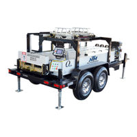
NTM SSQ MultiPro Operation And Maintenance Manual (118 pages)
PLC Controller. Quick Change - Commercial/Residential Roof Panel Machine
Brand:
NTM
| Category:
Cutter
| Size: 10 MB
Table of Contents
Table of Contents
2
Chapter 1 Specifications
6
Chapter 2 Precautions
7
Figure 1: Machine Orientation
8
Figure 2: Mounting Foot Detail
9
Chapter 3 General Mainenance
10
Recommended Lubricants and Fluids
11
Figure 3: Entry Guide
12
Figure 4: Acme Shafts and Left Side Adjustment
13
Electrical Controls and Operation
14
Figure 5: Controls
17
Figure 6: Main Control Cable
18
Figure 7: Run out Table and Remote Limit Switch
19
Figure 8: Main Control Box Fuse
20
Figure 9: QCPP E 1-6 Fuse Location
20
Reel Stands, Reels and Expandable Arbors
21
Figure 10: Expandable Arbor Set-Up
22
Figure 11: Expandable Reel Assembly
24
Figure 12: Material Routing
26
Maintenance
27
Hydraulic Fluid Troubleshooting
27
Changing Hydraulic Fluid and Filter
27
Hydraulic Systems
27
Figure 13: Hydraulic System - Overview
28
Figure 14: Hydraulic System - Details
29
Figure 15: Hydraulic Fluid Level
30
Drive System
31
Figure 16: Drive Roll Assembly View
32
Figure 17: Gears and Shafts
33
Figure 18: Chains Upper and Lower
34
Shear Assembly
35
Figure 19: Entry/Exit Views
36
Figure 20: Shear die Detail Views
37
Bead and Striation Roller Assembly
39
Figure 21: Bead Roller Assembly
40
Figure 22: Right Entry Guide
41
Entry Guide Adjustment
41
Figure 23: Entry Guide Assembly
42
Figure 24: Tooling Rail Adjustment Handle
43
Figure 25: Marker Plate & Alignment Pin
43
Figure 26: Disengaged
43
Figure 27: Engaged
43
Figure 28: Clip Relief Roller Assembly
44
Figure 29: Entry Drum
45
Chapter 12
45
Chapter 13 Entry Drum Assembly
45
Chapter 14 Width Change Procedure
46
Figure 31: Expandable Arbor Setup
47
Figure 32: Loading Material
48
Figure 33: Bead Roller Alignment
49
Figure 34: Bead Roller Width Change
50
Figure 35: Shear Bolts
51
Figure 36: Exit die Adjustment
52
Chapter 15 Profile Changeover Procedure
54
Figure 38: Removing Tooling Rails
55
Figure 39: Block Chart
55
Figure 40: Inboard/Outboard Positions
56
Figure 41: April 2009 and Later
57
Figure 42: Machines Made before April 2009
57
Figure 43: Right Side Fixed Mount Rail
58
Figure 44: Profile Chart
58
Figure 45: Left Side Fixed Mount Rail
59
Figure 46: Shown in the "A" Position
59
Figure 47: Tooling Rail Identification
60
Figure 48: R1 Tooling Rail Spacers
60
Figure 49: L1-1 Special Instructions
61
Figure 50: Entry Guide Alignment Notches and Pins
62
Figure 51: Tooling Rail Adjustment Handle
62
Figure 52: Marker Plate Notch and Pin
63
Figure 53: Preparing Coil for Loading
63
Figure 54: Jogging Material Thru Machine
64
Figure 55: Spacing Bead Rollers
64
Figure 56: Removing Shear Cover
65
Figure 57: Remove Shear Bolts
66
Figure 58: Exit die Adjustment
67
Chapter 16 Roller Systems and Panel Profile Drawings
68
Figure 60: SS100 Panel Profile
69
Figure 61: SSQ150 Roller System
70
Figure 62: SS150 Panel Profile
71
Figure 63: SSQ200/210A Roller System
72
Figure 64: SS200 Panel Profile
73
Figure 65: SS210 Panel Profile
74
Figure 66: SSQ450/450SL Roller System
75
Figure 67: SS450 Panel Profile
76
Figure 68: SS450SL Panel Profile
77
Figure 69: SSQ550 Roller System
78
Figure 70: SS550 Panel Profile
79
Figure 71: SSQ675 Roller System
80
Figure 72: SS675 Panel Profile
81
Figure 73: FFQ100 Roller System
82
Figure 74: FF100 Panel
83
Figure 75: FFQ150 Roller System
84
Figure 76: FF150 Panel Profile
85
Figure 77: SSQBP Roller System
86
Figure 78: BP 1" Panel
87
Figure 79: BP 1 1/2" Panel
88
Chapter 17 Run out Tables and Remote Limit Switch
89
Figure 80: Run out Table
90
Figure 81: Run out Table Setup
91
Chapter 18 Quick Change Power Pac
92
Figure 82: Cable Connections and Fasteners
93
Chapter 19 Troubleshooting
94
Figure 84: Limit Switch Adjustment
96
Appendex a
98
Appendex B
98
Figure 85: PLC Assembly
98
Figure 86: Serial Number Plate
98
Home
99
Manual Operation
99
Automatic Operation
99
Figure 87: Home Screen
99
Job Entry
100
Programming Jobs
100
Figure 88: Job Entry Screen
100
Clear Jobs
101
Auto Run
101
Figure 89: Specify Job to Run First
101
Figure 90: Auto-Run Screen
101
Automatic Operation
102
On the Fly Calibration
102
Calibration
102
Figure 91: Calibration Screen
102
Setup
103
Figure 92: Calibration Screen
103
Figure 93: Calibration Screen
103
Status/Diagnostics
104
Figure 94: Setup Screen
104
Figure 95: Status Screen
104
Security
105
Figure 96: Security Screen
105
Coil Tracking
106
Figure 97: Coils Password Access Screen
106
Figure 98: Coils Screen
106
Colors
107
Figure 99: Coil Indicator
107
Coil Length Calculator
108
Figure 100: Coils Color Screen
108
Figure 101: Length Calculator Screen
108
Figure 102: Material and Thickness Screen
109
Figure 103: Coil Dimensions
109
Figure 30: Entry Guide Bolts "A
46
Figure 37: Remove Top Covers
54
Figure 59: SSQ100 Roller System
68
Figure 83: Pressure Switch Adjustment
94
Advertisement
NTM SSQ MultiPro Operation And Maintenance Manual (116 pages)
Quick Change - Commercial/Residential Roof Panel Machine
Brand:
NTM
| Category:
Cutter
| Size: 10 MB
Table of Contents
Table of Contents
2
Chapter 1 Specifications
5
Chapter 2 Precautions
6
Figure 1: Machine Orientation
7
Figure 2: Mounting Foot Detail
8
Chapter 3 General Mainenance
9
Recommended Lubricants and Fluids
10
Figure 3: Entry Guide
11
Figure 4: Acme Shafts and Left Side Adjustment
12
Electrical Controls and Operation
13
Figure 5: Controls
16
Figure 6: Control Cables
17
Figure 7: Run out Table and Remote Limit Switch
18
Figure 8: Main Control Box Fuse
19
Figure 9: QCPP E 1-6 Fuse Location
19
Reel Stands, Reels and Expandable Arbors
20
Figure 10: Expandable Arbor Set-Up
21
Figure 11: Expandable Reel Assembly
23
Figure 12: Material Routing
25
Maintenance
26
Hydraulic Fluid Troubleshooting
26
Changing Hydraulic Fluid and Filter
26
Hydraulic Systems
26
Figure 13: Hydraulic System - Overview
27
Figure 14: Hydraulic System - Details
28
Figure 15: Hydraulic Fluid Level
29
Drive System
30
Figure 16: Drive Roll Assembly View
31
Figure 17: Gears and Shafts
32
Figure 18: Chains Upper and Lower
33
Shear Assembly
34
Figure 19: Entry/Exit Views
35
Figure 20: Shear die Detail Views
36
Bead and Striation Roller Assembly
38
Figure 21: Bead Roller Assembly
39
Figure 22: Right Entry Guide
40
Entry Guide Adjustment
40
Figure 23: Entry Guide Assembly
41
Figure 24: Tooling Rail Adjustment Handle
42
Figure 25: Marker Plate & Alignment Pin
42
Figure 26: Disengaged
42
Figure 27: Engaged
42
Figure 28: Clip Relief Roller Assembly
43
Figure 29: Entry Drum
44
Chapter 12
44
Chapter 13 Entry Drum Assembly
44
Chapter 14 Width Change Procedure
45
Figure 31: Expandable Arbor Setup
46
Figure 32: Loading Material
47
Figure 33: Bead Roller Alignment
48
Figure 34: Bead Roller Width Change
49
Figure 35: Shear Bolts
50
Figure 36: Exit die Adjustment
51
Chapter 15 Profile Changeover Procedure
53
Figure 38: Removing Tooling Rails
54
Figure 39: Block Chart
54
Figure 40: Inboard/Outboard Positions
55
Figure 41: April 2009 and Later
56
Figure 42: Machines Made before April 2009
56
Figure 43: Right Side Fixed Mount Rail
57
Figure 44: Profile Chart
57
Figure 45: Left Side Fixed Mount Rail
58
Figure 46: Shown in the "A" Position
58
Figure 47: Tooling Rail Identification
59
Figure 48: R1 Tooling Rail Spacers
59
Figure 49: L1-1 Special Instructions
60
Figure 50: Entry Guide Alignment Notches and Pins
61
Figure 51: Tooling Rail Adjustment Handle
61
Figure 52: Marker Plate Notch and Pin
62
Figure 53: Preparing Coil for Loading
62
Figure 54: Jogging Material Thru Machine
63
Figure 55: Spacing Bead Rollers
63
Figure 56: Removing Shear Cover
64
Figure 57: Removing Photo Eye and Bracket (if Equipped)
65
Figure 58: Remove Shear Bolts
65
Figure 59: Exit die Adjustment
66
Chapter 16 Roller Systems and Panel Profile Drawings
68
Figure 61: SS100 Panel Profile
69
Figure 62: SSQ150 Roller System
70
Figure 63: SS150 Panel Profile
71
Figure 64: SSQ200/210A Roller System
72
Figure 65: SS200 Panel Profile
73
Figure 66: SS210 Panel Profile
74
Figure 67: SSQ450/450SL Roller System
75
Figure 68: SS450 Panel Profile
76
Figure 69: SS450SL Panel Profile
77
Figure 70: SSQ550 Roller System
78
Figure 71: SS550 Panel Profile
79
Figure 72: SSQ675 Roller System
80
Figure 73: SS675 Panel Profile
81
Figure 74: FFQ100 Roller System
82
Figure 75: FF100 Panel
83
Figure 76: FFQ150 Roller System
84
Figure 77: FF150 Panel Profile
85
Figure 78: SSQBP Roller System
86
Figure 79: BP 1" Panel
87
Figure 80: BP 1 1/2" Panel
88
Chapter 17 Run out Tables and Remote Limit Switch
89
Figure 81: Run out Table
90
Figure 82: Run out Table Setup
91
Chapter 18 Quick Change Power Pac
92
Figure 83: Cable Connections and Fasteners
93
Chapter 19 Troubleshooting
94
Figure 85: Limit Switch Adjustment
96
Figure 86: AMS Box Without Cables
98
Computer Batch and Length Controller
98
Introduction
99
Figure 87: AMS Box with Cables
99
Figure 88: AMS Controls MP465 Controller
99
Manual Operations
100
Production Procedures
100
Administrative Screens and Functions
103
Troubleshooting
104
Electrical Schematics
107
Figure 30: Entry Guide Bolts "A
45
Figure 37: Remove Top Covers
53
Figure 60: SSQ100 Roller System
68
Figure 84: Pressure Switch Adjustment
94
Advertisement
Related Products
NTM SSR multiPro Jr
NTM SSH MultiPro
NTM Categories
Cutter
Industrial Equipment
Construction Equipment
Controller
More NTM Manuals
Login
Sign In
OR
Sign in with Facebook
Sign in with Google
Upload manual
Upload from disk
Upload from URL