Sign In
Upload
Manuals
Brands
NTM Manuals
Industrial Equipment
SSH MultiPro
NTM SSH MultiPro Manuals
Manuals and User Guides for NTM SSH MultiPro. We have
1
NTM SSH MultiPro manual available for free PDF download: Operation And Maintenance Manual
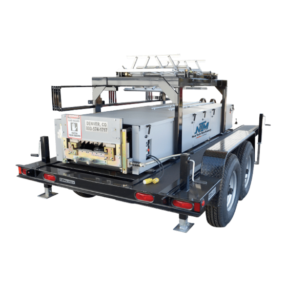
NTM SSH MultiPro Operation And Maintenance Manual (92 pages)
Roof Panel Machine
Brand:
NTM
| Category:
Industrial Equipment
| Size: 5 MB
Table of Contents
Table of Contents
2
Figure 2: Mounting Foot Detail
9
Chapter 2 Chapter 3..........Machine Orientation ........................................................................... 5 Chapter 4..........General Maintenance ......................................................................... 7
11
Chapter 3 Chapter 4..........General Maintenance ......................................................................... 7
11
Chapter 4
11
Recommended Lubricants and Fluids
11
Figure 3: Controls
15
Figure 4: Main Control Cable
16
Figure 5: Run out Table and Remote Limit Switch
17
Figure 6: Main Control Box Fuse
18
Figure 7: QCPP E 1-6 Fuse Location
18
Figure 8: Expandable Arbor Set-Up
20
Figure 9: Expandable Reel Assembly
22
Figure 10: Material Routing
24
Chapter 1 Chapter 2...........Precautions .............................................................................................. 4 Chapter 3..........Machine Orientation ........................................................................... 5 Chapter 4..........General Maintenance ......................................................................... 7
11
Chapter 5 Chapter 6..........Reel Stands, Reels and Expandable Arbors ......................... 16 Chapter 7..........Hydraulic Systems ............................................................................. 22
25
Chapter 6 Chapter 7..........Hydraulic Systems ............................................................................. 22
25
Chapter 7
25
Maintenance
25
Hydraulic Fluid Troubleshooting
25
Changing Hydraulic Fluid and Filter
25
Figure 11: Hydraulic System Overview
26
Figure 12: Hydraulic System - Details
27
Figure 13: Hydraulic Fluid Level
27
Figure 14: Drive Roll Assembly
29
Figure 15: Sprockets and Shafts
30
Figure 16: Upper and Lower Chains
31
Figure 17: Entry/Exit Views
33
Figure 18: Shear die Detail Views
34
Figure 19: Bead Roller Assembly
37
Figure 20: Clip Relief Roller Assembly
38
Figure 21: Entry Drum
39
Chapter 8 Chapter 9.........Shear Assembly .................................................................................... 29 Chapter 10........Bead And Striation Roller Assembly ...................................... 33 Chapter 11........Clip Relief Roller Assembly .......................................................... 35
40
Chapter 9 Chapter 10........Bead And Striation Roller Assembly ...................................... 33 Chapter 11........Clip Relief Roller Assembly .......................................................... 35 Chapter 12........Entry Drum Assembly ....................................................................... 36
40
Chapter 11 Chapter 12........Entry Drum Assembly ....................................................................... 36 Chapter 13........Width And Profile Change Procedure ..................................... 37
40
Chapter 13
40
Tooling Changeover
40
Figure 22: Remove Covers
41
Figure 23: Tooling Rail Detail
42
Entry Guide Adjustment
43
Figure 24: Entry Guide
44
Tooling Rail to Entry Guide Alignment
45
Shear Changeover
45
Loading Machine with Material
45
Figure 25: Feeding Material into Entry Guides
46
Figure 26: Material Entering Bead Rollers
46
Bead Rollers (if Equipped)
47
Shear Alignment
47
Figure 27: Exit die Adjustment
48
Figure 29: Run out Table Setup
51
Figure 32: Top of Stroke Limit Switch
55
Figure 33: Limit Switch Adjustment Screws
55
Figure 34: SSH100 Roller System
57
Figure 35: SS100 Panel Profile
58
Figure 36: SSH150 Roller System
59
Figure 37: SS150 Panel Profile
60
Figure 38: SSH450/450SL Roller System
61
Figure 39: SS450 Panel Profile
62
Figure 40: SS450SL Panel Profile
63
Figure 41: FFH100 Roller System
64
Figure 42: FF100 Panel Profile
65
Figure 43: FFH150 Roller System
66
Figure 44: FF150 Panel Profile
67
Figure 45: BP1 Roller System
68
Figure 46: BP1 Panel Profile
69
Figure 47: BP15 Roller System
70
Figure 48: BP15 Panel Profile
71
Figure 49: PLC Assembly
72
Figure 50: Serial Number Plate
72
Chapter 12 Chapter 13........Width And Profile Change Procedure ..................................... 37
40
Chapter 10 Chapter 11........Clip Relief Roller Assembly .......................................................... 35 Chapter 12........Entry Drum Assembly ....................................................................... 36 Chapter 13........Width And Profile Change Procedure ..................................... 37
40
Chapter 14 Chapter 15........Quick Change Power Pac .................................................................. 49 Chapter 16........Troubleshooting ................................................................................. 51 Chapter 17........Roller Systems and Panel Profile Drawings ...................... 54
73
Chapter 15 Chapter 16........Troubleshooting ................................................................................. 51 Chapter 17........Roller Systems and Panel Profile Drawings ...................... 54 Appendex A........plc Controller ....................................................................................... 1
73
Chapter 16 Chapter 17........Roller Systems and Panel Profile Drawings ...................... 54 Appendex A........plc Controller ....................................................................................... 1
73
Chapter 17 Appendex A........plc Controller ....................................................................................... 1
73
Home
73
Manual Operation
73
Automatic Operation
73
Figure 51: Home Screen
73
Job Entry
74
Programming Jobs
74
Figure 52: Job Entry Screen
74
Clear Jobs
75
Auto Run
75
Figure 53: Specify Job to Run First
75
Figure 54: Auto-Run Screen
75
Automatic Operation
76
On the Fly Calibration
76
Calibration
76
Figure 55: Calibration Screen
76
Setup
77
Figure 56: Calibration Screen
77
Figure 57: Calibration Screen
77
Status/Diagnostics
78
Figure 58: Setup Screen
78
Figure 59: Status Screen
78
Security
79
Figure 60: Security Screen
79
Coil Tracking
80
Figure 61: Coils Password Access Screen
80
Figure 62: Coils Screen
80
Colors
81
Figure 63: Coil Indicator
81
Coil Length Calculator
82
Figure 64: Coils Color Screen
82
Figure 65: Length Calculator Screen
82
Figure 66: Material and Thickness Screen
83
Figure 67: Coil Dimensions
83
Advertisement
Advertisement
Related Products
NTM SSQ MultiPro
NTM SSR multiPro Jr
NTM BG7
NTM Categories
Cutter
Industrial Equipment
Construction Equipment
Controller
More NTM Manuals
Login
Sign In
OR
Sign in with Facebook
Sign in with Google
Upload manual
Upload from disk
Upload from URL