Sign In
Upload
Manuals
Brands
NSC Sicherheitstechnik Manuals
Control Panel
Solution F1
NSC Sicherheitstechnik Solution F1 Manuals
Manuals and User Guides for NSC Sicherheitstechnik Solution F1. We have
1
NSC Sicherheitstechnik Solution F1 manual available for free PDF download: Operating And Installation Manual
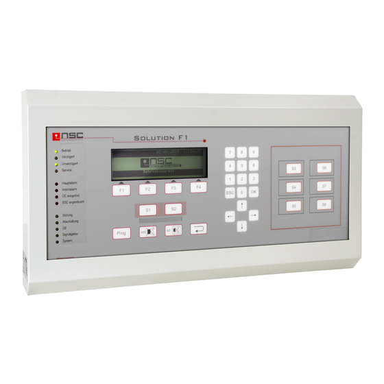
NSC Sicherheitstechnik Solution F1 Operating And Installation Manual (69 pages)
Fire Control Panel
Brand:
NSC Sicherheitstechnik
| Category:
Control Panel
| Size: 0 MB
Table of Contents
Table of Contents
3
1 Description of Control Panel
7
LED Indications
7
LC Module Indications
8
Description of the Push Buttons
9
2 Menus for the End User
10
General Main Menu for End User
10
FCP Selection
10
Main Menu "Switch on / Switch off
10
Alarm Counter
11
Changing the End User Access Code
11
Diagnosis Menu
11
Switching On/Off: Zones and Single Detectors
12
Switching On/Off: OC-Outputs
12
Switching On/Off: 4 Internal Relays
12
Switching On/Off: 3 Internal Power Outputs
13
Switching On/Off: Sounders / Strobes
13
Switching On/Off: Alarm Transmission Device (TD)
13
Switching On/Off: Alarm Transmission Delay
14
Switching On/Off: Fire Outputs
14
Event Memory
14
Detector Data
14
Internal Modules (Pcbs) : Overview
15
Network Data
15
Example of Power Supply Voltages
15
Example of Power Supply Status Information
16
Example of Power Outputs Voltages
16
Example of Input Voltages
16
Example of Displaying Software Version and Serial no
16
Switching On/Off: Addressable Detectors
17
Event Memory: "Filter
17
Event Memory: "Printing
17
Table of Detectors
17
Internal Modules (Pcbs): Details
20
Display of Network Adapters
20
Modem Data
20
Display of FRP/LCD Panel
21
Display of Modbus Devices
21
Details of Network Devices
21
Detector Details of Network Devices
22
Example of Detector Data: MCP
22
Example of Detector Data: Optical Smoke Detector
23
Example of Detector Data: Listec Heat Sensor Cable SEC15
24
Example of Loop Card Details
24
Example of Details of a Fire Brigade Repeater Panel with Fire Brigade Control Panel
24
Only for Hochiki ESP
24
Example of "Zero Point" and "Fire Point" Display
24
Only for Apollo Discovery
25
3 Installer Menus
26
Access to the Installer Menu
27
General Main Menu for Installer
27
Main Menu: Test Functions
28
Main Menu: Automatic Controlling
28
Main Menu: Alarm Configuration
28
Settings 1 of FCP
29
Settings 2 of FCP
29
Settings 3Of FCP
30
Detector Test (Only for Addressable Detectors)
30
Menu "Manual Controlling
31
Menu "Simulation
31
Menu "Revision
31
Automatic Control: Internal OC Outputs
32
Automatic Control: 4 Internal Relays
32
Automatic Control: 3 Monitored Power Outputs
32
Automatic Control: Output Modules (Loop)
32
Automatic Control: Input Modules (Loop)
33
Automatic Control: 8 Resistor Monitored Inputs
33
Automatic Control: 2 Monitored, Conventional Inputs
34
Select the Kind of Detectors to Configure: Loop or Conventional
34
Detector Settings
34
Zone Settings
34
Zone Alarm Coincidences
35
Timer Programs
35
Delay Times of Main Alarm (TD)
36
To Set Date and Time
36
To Configure Holidays
37
System Settings
37
Scan Detectors
39
Delete Configuration
39
Delete Texts
39
Delete Events
39
Configuring Macro Push Buttons S1 - S8
39
Changing the Installer Access Code
40
Selecting the Panel Language
40
Configuring the Interfaces
40
Alarm and Fault Thresholds for Conventional Detectors
40
Scanning RS485 Devices
41
Modem Functions
41
Network Settings
41
Flash Update
42
Power Outputs: Thresholds
42
Loop Parameters
43
Options
43
ESPA 4.4.4 Settings
43
Arcnet Baud Rate
44
Sections
44
Network Sections
44
FRP Protocol Sections
44
Webserver Settings
44
Manual Control: Internal OC Outputs
45
Manual Control: 4 Internal Relays
45
Manual Control: 3 Monitored Power Outputs
46
Manual Control: Output Modules (Loop)
46
Automatic Control: Settings for Outputs
46
Automatic Control: Functions
47
Selection of Displaying Cause and Effect Events
47
Automatic Control: Settings for Output Modules (Loop)
48
Automatic Control: Settings for Sounders/ Sounder Modules (Loop)
48
Automatic Control: Settings of 8 Internal Monitored Inputs
49
Configuring Zones (Loop)
49
Configuring Conventional Zones
50
Analogue Addressable Detector's Sensitivity / Modes / Delays
50
To Configure Timer Programs
52
Interface Protocols
52
Interface Baud Rates
53
Configuring Thresholds for Conventional Detectors
53
Maintenance
53
Push Button S_ Settings
53
Zone Leds
53
Configuring the Timer
54
Cause and Effect Events List
54
Cause and Effect Events Configuration
54
Event Codes
55
4 Mounting Instruction
57
5 Commissioning Certificate FCP "Solution F1
58
General
58
Checking the Documentation
58
Checking the System Components
58
Checking the Wiring System
59
Measure End of Line Resistors of Conventional Zones (Without Voltage)
59
Measure Cable Resistance of Loop Wiring (Without Voltage)
59
Measurement of the End of Line Resistors of the Monitored Power Outputs (Without Voltage)
60
Measurement of the End of Line Resistors of the Monitored Inputs (Without Voltage)
60
Checking the End of Line Resistor on the RS485 Bus
60
Commissioning of the Power Supply
60
Scanning of Internal an External Components
61
Detector Modules
61
Serial Devices
61
Addressable Detectors/Modules
62
Checking of Earth Fault
63
Measurement of Loop Voltage and Current
63
Configure Power Outputs
64
Configuration of the Fire Control System
64
Functional Tests
65
6 Technical Specifications
66
Power Supply
66
Common Technical Data
67
Minimum/ Maximum Voltages/Currents
68
Fuse Values
68
Cable Parameter
68
7 CE Marking
69
Advertisement
Advertisement
Related Products
NSC Sicherheitstechnik Solution F2
NSC Sicherheitstechnik Categories
Speakers
Control Panel
Emergency Phone
More NSC Sicherheitstechnik Manuals
Login
Sign In
OR
Sign in with Facebook
Sign in with Google
Upload manual
Upload from disk
Upload from URL