Table of Contents
Advertisement
Quick Links
Advertisement
Table of Contents

Related Manuals for NSC Sicherheitstechnik Solution F1

Summary of Contents for NSC Sicherheitstechnik Solution F1
- Page 1 Fire Control Panel "Solution F1" Operating and Installation Manual Issue: August 2013 NSC Sicherheitstechnik GmbH 1/69 14.08.2013 Lange Wand 3 B01050 B01060 Operating Installation Manual Solution F1 20130814.doc 33719 Bielefeld Version S040A13.08...
- Page 2 NSC Sicherheitstechnik GmbH 2/69 14.08.2013 Lange Wand 3 B01050 B01060 Operating Installation Manual Solution F1 20130814.doc 33719 Bielefeld Version S040A13.08...
-
Page 3: Table Of Contents
Access to the installer menu ....................27 General Main menu for installer ....................27 Main menu: Test functions ....................... 28 Main menu: Automatic Controlling ................... 28 NSC Sicherheitstechnik GmbH 3/69 14.08.2013 Lange Wand 3 B01050 B01060 Operating Installation Manual Solution F1 20130814.doc 33719 Bielefeld Version S040A13.08... - Page 4 Automatic Control: Settings of 8 internal monitored inputs ............49 Configuring zones (loop) ......................49 Configuring conventional zones ....................50 NSC Sicherheitstechnik GmbH 4/69 14.08.2013 Lange Wand 3 B01050 B01060 Operating Installation Manual Solution F1 20130814.doc 33719 Bielefeld Version S040A13.08...
- Page 5 Power Supply ........................... 66 Common technical data......................67 Minimum/ maximum voltages/currents..................68 Fuse values ..........................68 Cable parameter........................68 CE marking:..........................69 NSC Sicherheitstechnik GmbH 5/69 14.08.2013 Lange Wand 3 B01050 B01060 Operating Installation Manual Solution F1 20130814.doc 33719 Bielefeld Version S040A13.08...
- Page 6 NSC Sicherheitstechnik GmbH 6/69 14.08.2013 Lange Wand 3 B01050 B01060 Operating Installation Manual Solution F1 20130814.doc 33719 Bielefeld Version S040A13.08...
-
Page 7: Description Of Control Panel
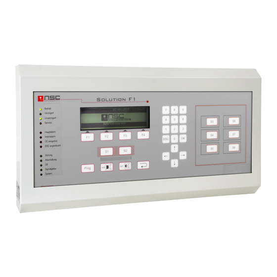
1. Description of Control Panel : Picture of the control panel of the "Solution F1": LED indications Dynamic functions keys F1 – F4, Field programmable push buttons S1 – S8 The functions is individually indicated and mounting place for printer in the bottom line of the LC module Key ‘Prog’: to select the main menu... -
Page 8: Lc Module Indications
If the user enters one of the menus (by pressing the push button "Prog") at the bottom line of the LC module he sees the dynamic function keys F1 – F4. Sometimes all 4 keys are used, sometimes only NSC Sicherheitstechnik GmbH 8/69 14.08.2013 Lange Wand 3 B01050 B01060 Operating Installation Manual Solution F1 20130814.doc 33719 Bielefeld Version S040A13.08... -
Page 9: Description Of The Push Buttons
Description of the push buttons: The control panel of the FCP "Solution F1" contains a brand new technology of push buttons. There are no more mechanical push buttons or ordinary foil key pads but it is a pressure sensitive piezo lacquer technology which is printed on the aluminum plate. -
Page 10: Menus For The End User
Switching on/off of Relays inside the FCP Jump to Menu Cancel Enter Switching on/off of 3 monitored power outputs Jump to Menu NSC Sicherheitstechnik GmbH 10/69 14.08.2013 Lange Wand 3 B01050 B01060 Operating Installation Manual Solution F1 20130814.doc 33719 Bielefeld Version S040A13.08... -
Page 11: Alarm Counter
8 monitored inputs. You can check fault messages here Example in Picture To display FCP Software version and Serial Example in Picture NSC Sicherheitstechnik GmbH 11/69 14.08.2013 Lange Wand 3 B01050 B01060 Operating Installation Manual Solution F1 20130814.doc 33719 Bielefeld Version S040A13.08... -
Page 12: Switching On/Off: Zones And Single Detectors
RCP 003 from output : 001 normal Here the 16 OC-outputs on the main processor board of to output the FCP "Solution F1” as well as the OC-outputs on the ↓+1 ↑-1 Selection -> +10 <- -10 loop cards can be switched on/off. -
Page 13: Switching On/Off: 3 Internal Power Outputs
Switch on/off FCP 001 from power output : 001 normal Here the 3 internal power outputs on the main to power output processor board of the FCP "Solution F1” can be ↓+1 ↑-1 Selection -> +10 <- -10 switched on/off. -
Page 14: Switching On/Off: Alarm Transmission Delay
0005 which were found during last loop scanning. 0006 Cancel Segment Details The right column "config." shows the number of NSC Sicherheitstechnik GmbH 14/69 14.08.2013 Lange Wand 3 B01050 B01060 Operating Installation Manual Solution F1 20130814.doc 33719 Bielefeld Version S040A13.08... -
Page 15: Internal Modules (Pcbs) : Overview
"0" means highest sensitivity, "10" means lowest sensitivity for fault message display. NSC Sicherheitstechnik GmbH 15/69 14.08.2013 Lange Wand 3 B01050 B01060 Operating Installation Manual Solution F1 20130814.doc 33719 Bielefeld Version S040A13.08... -
Page 16: Example Of Power Supply Status Information
In this example key "S2" is active. S3 S4 S5 S6 S7 S9 Cancel Leaving the menu by pressing F1 ("Cancel"). NSC Sicherheitstechnik GmbH 16/69 14.08.2013 Lange Wand 3 B01050 B01060 Operating Installation Manual Solution F1 20130814.doc 33719 Bielefeld Version S040A13.08... -
Page 17: Switching On/Off: Addressable Detectors
If only one detector shall be switched the line "to detector" can be missed and F2/F3 (on/off) can be pressed immediately. Event memory: "Filter" Filter The FCP Solution F1 saves all messages in their 1. Alarm x 5. Off event memory. 2. Pre alarm x 6. - Page 18 Manual Call Point Sounder/Beacon Sounder/Flash DISCOV. Voicesounder Voice Sounder DISCOV. Voicesounder/Beac Voice Sounder/Flash on DISCOV. opt. det. XP95 Optical smoke detector NSC Sicherheitstechnik GmbH 18/69 14.08.2013 Lange Wand 3 B01050 B01060 Operating Installation Manual Solution F1 20130814.doc 33719 Bielefeld Version S040A13.08...
- Page 19 Jump to Picture for Manual Call Points Jump to Picture for optical smoke detector NSC Sicherheitstechnik GmbH 19/69 14.08.2013 Lange Wand 3 B01050 B01060 Operating Installation Manual Solution F1 20130814.doc 33719 Bielefeld Version S040A13.08...
-
Page 20: Internal Modules (Pcbs): Details
"Gateway" is the address of the routers and has to be Cancel activated if external access to the webserver should be possible. NSC Sicherheitstechnik GmbH 20/69 14.08.2013 Lange Wand 3 B01050 B01060 Operating Installation Manual Solution F1 20130814.doc 33719 Bielefeld Version S040A13.08... -
Page 21: Display Of Frp/Lcd Panel
After 90 seconds a network fault will be displayed. The bit sequence "Status 1" contains the following status information from right to left: NSC Sicherheitstechnik GmbH 21/69 14.08.2013 Lange Wand 3 B01050 B01060 Operating Installation Manual Solution F1 20130814.doc 33719 Bielefeld Version S040A13.08... -
Page 22: Detector Details Of Network Devices
The "Output” bits show – in case of output modules – which outputs are active or in fault condition. Fault : missing Cancel NSC Sicherheitstechnik GmbH 22/69 14.08.2013 Lange Wand 3 B01050 B01060 Operating Installation Manual Solution F1 20130814.doc 33719 Bielefeld Version S040A13.08... -
Page 23: Example Of Detector Data: Optical Smoke Detector
(Discovery) or the alarm threshold (XP95, XPlorer) will be reset. Without Cancel Compens. Details manual compensation the FCP will adjust these NSC Sicherheitstechnik GmbH 23/69 14.08.2013 Lange Wand 3 B01050 B01060 Operating Installation Manual Solution F1 20130814.doc 33719 Bielefeld Version S040A13.08... -
Page 24: Example Of Detector Data: Listec Heat Sensor Cable Sec15
In the bar charts on the left hand the limits and the standard values for the different detector types are demonstrated. NSC Sicherheitstechnik GmbH 24/69 14.08.2013 Lange Wand 3 B01050 B01060 Operating Installation Manual Solution F1 20130814.doc 33719 Bielefeld Version S040A13.08... -
Page 25: Only For Apollo Discovery
1 = LED flashes, if detector is polled. • 0 = LED off, if detector is polled this function can be set by system-parameter 8 NSC Sicherheitstechnik GmbH 25/69 14.08.2013 Lange Wand 3 B01050 B01060 Operating Installation Manual Solution F1 20130814.doc 33719 Bielefeld Version S040A13.08... -
Page 26: Installer Menus
Please keep the installer code (access code) in a save place. It is the protection of the panel against wrong operation. After pressing the push button you will enter the main menu of the FCP "Solution F1". Then F3 ("Installer") please press to enter the installer menus. -
Page 27: Access To The Installer Menu
To configure the interfaces To configure conventional zones To scan RS485 devices Settings 1 Jump to Menu Settings 2 Jump to Menu NSC Sicherheitstechnik GmbH 27/69 14.08.2013 Lange Wand 3 B01050 B01060 Operating Installation Manual Solution F1 20130814.doc 33719 Bielefeld Version S040A13.08... -
Page 28: Main Menu: Test Functions
E.g. day and night sensitivity, Cancel Enter multi sensor modes, selecting timer programs for detectors, delay and pre-alarm NSC Sicherheitstechnik GmbH 28/69 14.08.2013 Lange Wand 3 B01050 B01060 Operating Installation Manual Solution F1 20130814.doc 33719 Bielefeld Version S040A13.08... -
Page 29: Settings 1 Of Fcp
Jump to Menu After pressing "5" the RS-485 devices connected to the RS-485 interfaces will be NSC Sicherheitstechnik GmbH 29/69 14.08.2013 Lange Wand 3 B01050 B01060 Operating Installation Manual Solution F1 20130814.doc 33719 Bielefeld Version S040A13.08... -
Page 30: Settings 3Of Fcp
0002/002 opt. det. ALG-E Evt. individual detector text ██████████████████████ A-Value 4,5%/m Pre alarm███████████████ 2,7%/m █████████████████ Alarm 3,4%/m Cancel Calib. Details NSC Sicherheitstechnik GmbH 30/69 14.08.2013 Lange Wand 3 B01050 B01060 Operating Installation Manual Solution F1 20130814.doc 33719 Bielefeld Version S040A13.08... -
Page 31: Menu "Manual Controlling
F3 ("Off") because an alarm of these zones will not be transmitted to the fire brigade. NSC Sicherheitstechnik GmbH 31/69 14.08.2013 Lange Wand 3 B01050 B01060 Operating Installation Manual Solution F1 20130814.doc 33719 Bielefeld Version S040A13.08... -
Page 32: Automatic Control: Internal Oc Outputs
B02460/61-00) have two separate outputs you can select the output (1 or 2) in the line "Output” and confirm by "OK”. NSC Sicherheitstechnik GmbH 32/69 14.08.2013 Lange Wand 3 B01050 B01060 Operating Installation Manual Solution F1 20130814.doc 33719 Bielefeld Version S040A13.08... -
Page 33: Automatic Control: Input Modules (Loop)
Press F4 ("Event") Jump to Menu (Menu 106 to configure cause and effects events when the output module has to activate) NSC Sicherheitstechnik GmbH 33/69 14.08.2013 Lange Wand 3 B01050 B01060 Operating Installation Manual Solution F1 20130814.doc 33719 Bielefeld Version S040A13.08... -
Page 34: Automatic Control: 2 Monitored, Conventional Inputs
1. Analogue Detect. Here you select the kind of detectors which shall be 2. Convent. Detect. configured: analogue addressable or conventional. The FCP "Solution F1" has the ability not only to configure analogue addressable detectors but Cancel Enter conventional detectors too. That means you can assign to every hardware output for conventional detectors a software zone. -
Page 35: Zone Alarm Coincidences
Timer programs Timer programs 01/16 >Timer program The FCP "Solution F1" supports up to 16 different Timer program Night timer programs. Timer program Night A timer program has two different functions :... -
Page 36: Delay Times Of Main Alarm (Td)
This can be deactivated if you go to "System settings" (Menu 69) item 7. By pressing F3 ("Maintenance") a Maintenance interval can be configured. When this interval NSC Sicherheitstechnik GmbH 36/69 14.08.2013 Lange Wand 3 B01050 B01060 Operating Installation Manual Solution F1 20130814.doc 33719 Bielefeld Version S040A13.08... -
Page 37: To Configure Holidays
Switch off TD Switch on and off TD Mains fault 0-30 Minutes delay only with FBC 0-60 Minutes Switzerland (s. Parameter 1) NSC Sicherheitstechnik GmbH 37/69 14.08.2013 Lange Wand 3 B01050 B01060 Operating Installation Manual Solution F1 20130814.doc 33719 Bielefeld Version S040A13.08... - Page 38 0 = CR (NSC Parameter "printer" controls the line feed of a built in printer) connected printer. 1 = CRLF (ext. printer) NSC Sicherheitstechnik GmbH 38/69 14.08.2013 Lange Wand 3 B01050 B01060 Operating Installation Manual Solution F1 20130814.doc 33719 Bielefeld Version S040A13.08...
-
Page 39: Scan Detectors
The marker ">" indicates the push button which the user is configuring now. Then press F4 ("Event") jump to menu NSC Sicherheitstechnik GmbH 39/69 14.08.2013 Lange Wand 3 B01050 B01060 Operating Installation Manual Solution F1 20130814.doc 33719 Bielefeld Version S040A13.08... -
Page 40: Changing The Installer Access Code
ML thresholds. So nearly every detector on the fire market can be connected to the "Solution F1". Cancel The conventional detector PCBs inside the "Solution F1" are preset for Hochiki CDX detectors and Apollo S65/Orbis. -
Page 41: Scanning Rs485 Devices
Zone offset determines the starting number of zones for this FCP. Possible settings for Offset/Device no. are: NSC Sicherheitstechnik GmbH 41/69 14.08.2013 Lange Wand 3 B01050 B01060 Operating Installation Manual Solution F1 20130814.doc 33719 Bielefeld Version S040A13.08... -
Page 42: Flash Update
This total resistance can be Cancel Calib. save ascertained automatically for each power output individually by pressing "Calib." F3. The NSC Sicherheitstechnik GmbH 42/69 14.08.2013 Lange Wand 3 B01050 B01060 Operating Installation Manual Solution F1 20130814.doc 33719 Bielefeld Version S040A13.08... -
Page 43: Loop Parameters
The input range is 16 up to 40. The "Timeout" is a delay for a fault message in case of communication error (10-255 sec). NSC Sicherheitstechnik GmbH 43/69 14.08.2013 Lange Wand 3 B01050 B01060 Operating Installation Manual Solution F1 20130814.doc 33719 Bielefeld Version S040A13.08... -
Page 44: Arcnet Baud Rate
FCP the first time, the basic configuration has to be made by the function "Delete program". Alternatively the settings can be initialized by loading a NSC Sicherheitstechnik GmbH 44/69 14.08.2013 Lange Wand 3 B01050 B01060 Operating Installation Manual Solution F1 20130814.doc 33719 Bielefeld Version S040A13.08... -
Page 45: Manual Control: Internal Oc Outputs
Main board The way of operation is the same as in Menu 100. 003 Relay 003 Main board Cancel Enter NSC Sicherheitstechnik GmbH 45/69 14.08.2013 Lange Wand 3 B01050 B01060 Operating Installation Manual Solution F1 20130814.doc 33719 Bielefeld Version S040A13.08... -
Page 46: Manual Control: 3 Monitored Power Outputs
The value for the delay is in seconds and the possible range is 0 – 240 s. NSC Sicherheitstechnik GmbH 46/69 14.08.2013 Lange Wand 3 B01050 B01060 Operating Installation Manual Solution F1 20130814.doc 33719 Bielefeld Version S040A13.08... -
Page 47: Automatic Control: Functions
A cause and effect event is a link / configuration of Events for selection inputs and outputs combined with logical AND or OR. Cause and effect events are possible at the FCP "Solution F1" for OC outputs, relays, power outputs, Cancel Enter output modules, inputs, input modules und macro push buttons. -
Page 48: Automatic Control: Settings For Output Modules (Loop)
The tone can be varied from 0 (off) up to 7. See appendix C. (table of tones and volumes NSC Sicherheitstechnik GmbH 48/69 14.08.2013 Lange Wand 3 B01050 B01060 Operating Installation Manual Solution F1 20130814.doc 33719 Bielefeld Version S040A13.08... -
Page 49: Automatic Control: Settings Of 8 Internal Monitored Inputs
Please confirm every line by "OK” and after finishing all lines press "save" (F4) to save the new configuration. NSC Sicherheitstechnik GmbH 49/69 14.08.2013 Lange Wand 3 B01050 B01060 Operating Installation Manual Solution F1 20130814.doc 33719 Bielefeld Version S040A13.08... -
Page 50: Configuring Conventional Zones
Configuring conventional zones Zones Loop card When using the FCP "Solution F1" the conventional from ML zones are field programmable too : to ML from zone : 20 Please type the address of the conventional detector card (PCB). That means the DIL switch... - Page 51 Optical smoke detector Discovery Sens. Alarm Minimum time to threshold alarm 5 Sec. 30 Sec. 5 Sec. 30 Sec. 5 Sec. NSC Sicherheitstechnik GmbH 51/69 14.08.2013 Lange Wand 3 B01050 B01060 Operating Installation Manual Solution F1 20130814.doc 33719 Bielefeld Version S040A13.08...
-
Page 52: To Configure Timer Programs
By pressing F3 ("Off") the protocol will be deactivated again. Press "save" (F4) to save the new configuration. NSC Sicherheitstechnik GmbH 52/69 14.08.2013 Lange Wand 3 B01050 B01060 Operating Installation Manual Solution F1 20130814.doc 33719 Bielefeld Version S040A13.08... -
Page 53: Interface Baud Rates
By F1 ("Cancel") you will jump to the former menu. Cancel save By F4 ("save") the settings will be saved. NSC Sicherheitstechnik GmbH 53/69 14.08.2013 Lange Wand 3 B01050 B01060 Operating Installation Manual Solution F1 20130814.doc 33719 Bielefeld Version S040A13.08... -
Page 54: Configuring The Timer
If you want to configure a new event you have to put the marker on a "free” event and type "Enter” (F4”) Jump to Menu The FCP "Solution F1-6 and F1-18" support up to 2048 events. The user can also "delete" (F3) events and "insert”... -
Page 55: Event Codes
Outputs can be activated / deactivated by 3.Testalarm any of the available 16 timer programs automatically. 4.Activation Cancel more Enter NSC Sicherheitstechnik GmbH 55/69 14.08.2013 Lange Wand 3 B01050 B01060 Operating Installation Manual Solution F1 20130814.doc 33719 Bielefeld Version S040A13.08... - Page 56 Code "Installer" is the same for installer password. Codes for special keys Code 1. Switch on/off 2. Change sensit. 3. Activation Cancel Enter NSC Sicherheitstechnik GmbH 56/69 14.08.2013 Lange Wand 3 B01050 B01060 Operating Installation Manual Solution F1 20130814.doc 33719 Bielefeld Version S040A13.08...
-
Page 57: Mounting Instruction
/ strobes. 6. If you are connecting the shielding of the loop wires (the FCP "Solution F1" does NOT need that in any case but it can be advantageous to do so) then you have to connect the wire on both sides at the loop card. -
Page 58: Commissioning Certificate Fcp "Solution F1
Transmission device Fire brigade key deposit box Key deposit box release device Additional power supply Sounder Flashlight Telephone server SCU800 NSC Sicherheitstechnik GmbH 58/69 14.08.2013 Lange Wand 3 B01050 B01060 Operating Installation Manual Solution F1 20130814.doc 33719 Bielefeld Version S040A13.08... -
Page 59: Checking The Wiring System
(ML-5-/ML-6-) (ML-1-/ML-2-) (ML-5-/ML-6-) (ML-1-/ML-2-) (ML-5-/ML-6-) (ML-1-/ML-2-) (ML-5-/ML-6-) If the cable resistance is correct please plug the terminals in the FCP. NSC Sicherheitstechnik GmbH 59/69 14.08.2013 Lange Wand 3 B01050 B01060 Operating Installation Manual Solution F1 20130814.doc 33719 Bielefeld Version S040A13.08... -
Page 60: Measurement Of The End Of Line Resistors Of The Monitored Power Outputs (Without Voltage)
- switch on power supply for fire control panel! The internal buzzer will be on: please switch off by pressing NSC Sicherheitstechnik GmbH 60/69 14.08.2013 Lange Wand 3 B01050 B01060 Operating Installation Manual Solution F1 20130814.doc 33719 Bielefeld Version S040A13.08... -
Page 61: Scanning Of Internal An External Components
6. Modem 7. FBC/LCD panel 8. Modbus device Cancel Details Ο Ok Ο fault Number of installed serial devices correctly recognized? NSC Sicherheitstechnik GmbH 61/69 14.08.2013 Lange Wand 3 B01050 B01060 Operating Installation Manual Solution F1 20130814.doc 33719 Bielefeld Version S040A13.08... -
Page 62: Addressable Detectors/Modules
By pressing the "ok" key each single detector can be stored in the FCP programming, by pressing "all ok" all connected devices will be stored in the FCP flash memory simultaneously. NSC Sicherheitstechnik GmbH 62/69 14.08.2013 Lange Wand 3 B01050 B01060 Operating Installation Manual Solution F1 20130814.doc 33719 Bielefeld Version S040A13.08... -
Page 63: Checking Of Earth Fault
(ML-1-/ML-2-) (ML-5-/ML-6-) (ML-1-/ML-2-) (ML-5-/ML-6-) (ML-1-/ML-2-) (ML-5-/ML-6-) (ML-1-/ML-2-) (ML-5-/ML-6-) (ML-1-/ML-2-) (ML-5-/ML-6-) (ML-1-/ML-2-) (ML-5-/ML-6-) (ML-1-/ML-2-) (ML-5-/ML-6-) (ML-1-/ML-2-) (ML-5-/ML-6-) (ML-1-/ML-2-) (ML-5-/ML-6-) NSC Sicherheitstechnik GmbH 63/69 14.08.2013 Lange Wand 3 B01050 B01060 Operating Installation Manual Solution F1 20130814.doc 33719 Bielefeld Version S040A13.08... -
Page 64: Configure Power Outputs
Controlling by special keys Configuration Ο ok Ο not used System parameters Configuration Ο ok Ο not used Holidays Configuration NSC Sicherheitstechnik GmbH 64/69 14.08.2013 Lange Wand 3 B01050 B01060 Operating Installation Manual Solution F1 20130814.doc 33719 Bielefeld Version S040A13.08... -
Page 65: Functional Tests
Current of FCP at mains fault ....mA Required bridge over time ………….h Required battery capacity Ο Ok Ο fault …………Ah NSC Sicherheitstechnik GmbH 65/69 14.08.2013 Lange Wand 3 B01050 B01060 Operating Installation Manual Solution F1 20130814.doc 33719 Bielefeld Version S040A13.08... -
Page 66: Technical Specifications
Max. Battery internal resistance 400 m for all battery types Operating temperature: -5° C to +40° C Humidity: Max. 95% relative Humidness NSC Sicherheitstechnik GmbH 66/69 14.08.2013 Lange Wand 3 B01050 B01060 Operating Installation Manual Solution F1 20130814.doc 33719 Bielefeld Version S040A13.08... -
Page 67: Common Technical Data
IP 40 Dimensions housing A1, A2 : 540 x 492 x 162 mm (W x H x D) Weight FCP Solution F1-6 in housing A1, A2 : 14 kg Dimensions housing B1, B2 : 540 x 540 x 245 mm (W x H x D) -
Page 68: Minimum/ Maximum Voltages/Currents
500 mA time lag FBC Output 500 mA time lag Cable parameter Fire system cable All installation cables JY-(ST)Y-2x2x0,8 NSC Sicherheitstechnik GmbH 68/69 14.08.2013 Lange Wand 3 B01050 B01060 Operating Installation Manual Solution F1 20130814.doc 33719 Bielefeld Version S040A13.08... -
Page 69: Ce Marking
Test condition (EN54-2, Cl. 10) Standardized I/O interface (EN54-2, Cl. 11) For technical data see chapter 6 of this manual. NSC Sicherheitstechnik GmbH 69/69 14.08.2013 Lange Wand 3 B01050 B01060 Operating Installation Manual Solution F1 20130814.doc 33719 Bielefeld Version S040A13.08...
Need help?
Do you have a question about the Solution F1 and is the answer not in the manual?
Questions and answers