Sign In
Upload
Manuals
Brands
Novanta Manuals
Controller
ScanMaster
Novanta ScanMaster Manuals
Manuals and User Guides for Novanta ScanMaster. We have
1
Novanta ScanMaster manual available for free PDF download: User Manual
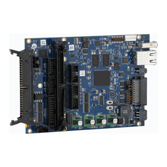
Novanta ScanMaster User Manual (103 pages)
Brand:
Novanta
| Category:
Controller
| Size: 2 MB
Table of Contents
Table of Contents
2
Table of Contents
3
Important Information
10
Safety Symbols
10
Safety Labels
11
Customer Support
11
Introduction
13
General Notes
13
Using this Manual
13
Purpose
13
Scope
13
Revision History
13
Revision History
14
List of Figures
15
Warranty Information
15
Product Introduction
16
System Description
16
List of Tables
17
Feature Overview
17
Hardware Features
17
Software Features
18
Technical Specifications
19
Installation
25
Storage and Operation Environment
25
Important
25
Electrical ESD Safety
25
Mechanical Layout
26
SMC, Auxiliary I/O, and High-Power Laser Adapter Assembly
27
System Configuration
28
SMC Main Module Mechanical Layout
28
SMC Interconnection Options
29
Connector Cross-Reference
30
SMC Connector Part Number Reference
30
SMC Module Connector Pinouts
31
Power Signal Pinouts (Connectors J1 and J3)
32
Connectors J1 and J3 (Power) Pinouts
32
Recommended Power Supply Connections
33
Connector J1 (Power) Signal Descriptions
33
Serial RS-232 Signal Pinouts (Connector J10)
34
Connector J10 (RS-232) Pinouts
34
Connector J3 (+24 Signal) Signal Descriptions
34
Connector J10 (RS-232) Signal Descriptions
34
XY2-100 Signal Pinouts (Connector J11)
35
Connector J11 (XY2-100) Pinouts
35
Connector J11 (XY2-100) Signal Descriptions
36
Auxiliary Signal Pinouts (Connector J13)
37
Connector J13 (Auxiliary) Pinouts
37
Connector J13 (Auxiliary) Signal Descriptions
38
MOTF-1 Signal Pinouts (Connector J14)
42
Connector J14 (MOTF-1) Pinouts
43
Connector J14 (MOTF-1) Signal Descriptions
43
MOTF-0 Signal Pinouts (Connector J15)
44
Connector J15 (MOTF-0) Pinouts
44
Connector J15 (MOTF-0) Signal Descriptions
44
Control Signal Pinouts (Connector J16)
45
Connector J16 (Control) Pinouts
46
Connector J16 (Control) Signal Descriptions
46
External Trigger Pinouts (Connector J17)
48
Connector J17 (External Trigger) Pinouts
48
Laser Signal Pinouts (Connector J18)
49
Connector J17 (External Trigger) Signal Descriptions
49
Connector J18 (Laser) Pinouts
50
Connector J18 (Laser) Signal Descriptions
50
E-STOP (Connector JP6)
53
Connector JP6 (E-STOP) Pinouts
54
Connector JP6 (E-STOP) Signal Descriptions
54
USB Port 1 Pinouts (Connector J5)
55
Connector J5 (USB Port 1 Pinouts)
55
Connector J5 (USB Port 1 Header) Signal Descriptions
55
USB Port 2 Header Pinouts (Connector J6)
56
Connector J6 (USB Port 2 Header) Pinouts
56
Signal Conditioning
57
Mark-On-The-Fly Inputs - J14 and J15
57
Signal Conditioning for Mark-On-The-Fly Inputs (J14 and J15)
57
Connector J6 (USB Port 2 Header) Signal Descriptions
57
High-Speed Laser Synchronization - J18
58
Laser Status 0-5 Signals - J18
58
General Purpose Inputs - J13 and J16
58
Signal Conditioning for High-Speed Laser Synchronization (J18)
58
Signal Conditioning for Laser Status 0-5 Signals (J18)
58
Signal Conditioning for General Purpose Inputs (J13 and J16)
58
System Control Inputs - J13 and J16
59
START Input - J17 and J15
59
Signal Conditioning for System Control Inputs (J13 and J16)
59
Signal Conditioning for START Input (J17 and J15)
59
System Control Outputs and General Purpose Outputs - J13 and J16
60
Signal Conditioning for System Control and General O/P (J13 & J16)
60
Laser Control Outputs - J18
61
Expected Usage of Digital Outputs
61
Signal Conditioning for Laser Control Outputs (J18)
61
Auxiliary XY2-100 Signals - J13
62
Signal Conditioning for Auxiliary XY2-100 Signals (J13)
62
Appendix A - Smc-Io-01 Auxiliary I/Omodule
63
Introduction
63
Mechanical Layout
64
Connectors
64
J3 and J4 - Xy2 - 100 Ports
64
Auxiliary I/O Module Outline Drawing
64
J11 - RS - 485 Communications
65
J10 - RS - 232 Communications
66
J11 RS-485 Communications
66
J15 and J16 - MOTF 0 and MOTF
67
J10 RS-232 Communications
67
J15 MOTF Port 0 (X) and J16 MOTF Port 1 (Y)
67
J6 and J8 - Extended Digital Inputs
68
Extended Inputs Signal Conditioning
68
J7 and J9 - Extended Digital Outputs
70
J13 and J14 - External Motor Control
72
Extended Outputs Signal Conditioning
72
J5 and J12 - System Control Inputs and Outputs
73
J5 System Control Inputs
73
J12 System Control Outputs
74
Appendix B - SMC-LSR-01 IPG Laser Adapter
75
Introduction
75
Mechanical Layout
75
IPG Laser Adapter Cable Mechanical Layout
75
Connectors
76
Laser Signal Mappings
76
SMC-LSR-01 Usage with IPG YLP-HP Type B Interface
77
IPG Laser Adapter Cable Signal Mappings
77
Modifications of SMC-LSR-01 for IPG YLP-HP Type B Connection
78
Connector JP6 (E-STOP) Pinouts
79
Custom Cable Pinouts for IPG YLP-HP Type B Interface
80
Appendix C - SMC-LSR-02 SPI Laser Adapter
82
Introduction
82
Mechanical Layout
83
Connectors
83
J2 SPI Laser Connector
83
SPI Laser Adapter Mechanical Layout
83
J3 E-STOP Connector
84
SPI Laser Connector Signal Assignments
84
E-STOP Connector Signal Assignments
85
Appendix D - SMC-LRS-04 High-Power Laser Adapter
86
Introduction
86
Mechanical Layout
87
Connectors
87
High-Power Laser Adapter Mechanical Layout
87
J2 - Laser Signal Set
88
Laser Signal Set 1
88
J3 - Laser Signal Set
89
Laser Signal Set 2
89
J5 BNC Laser Modulation Output
90
Local Laser Modulation Control
90
Selective Pull-Up/Pull-Down of Control Signals
91
Remote Modulation Control Configuration
91
Control Signal Pull-Up/Pull-Down Configuration
91
Appendix E - SMC-LSR-05 Coherent C70 Laser Adapter
92
Introduction
92
Mechanical Layout
93
Connectors
93
J5 - RJ-45 Laser Control Signals
93
Coherent C70 Laser Adapter Mechanical Layout
93
Laser Control Signals
93
J2 - Auxiliary Laser Control Signals
94
Auxiliary Laser Control Signals
94
Local Laser Modulation Control
95
Remote Modulation Control Configuration
96
Appendix F - XY2-100 Protocol Interface
97
Connections and Signal Descriptions
97
Connector to an XY2-100-Based Scan Head
97
Clock
98
Sync
98
X, Y, & Z Data
98
X2-100 Timing Diagram
98
Status Data
99
Index
101
Advertisement
Advertisement
Related Products
Novanta Scan Head
Novanta Synrad ti Series
Novanta gem with smd24
Novanta gem with smd12
Novanta SUB-10045
Novanta SUB-10041
Novanta ATI EtherCAT Sano74
Novanta ARGNET ASC-1
Novanta ARGNET ASC-2 V41
Novanta ARGNET ASC-6 V41
Novanta Categories
Measuring Instruments
Engine
Industrial Equipment
Medical Equipment
Control Unit
More Novanta Manuals
Login
Sign In
OR
Sign in with Facebook
Sign in with Google
Upload manual
Upload from disk
Upload from URL