
Related Manuals for Novanta ScanMaster

Summary of Contents for Novanta ScanMaster
- Page 1 ScanMaster Controller Advanced Laser Positioning and Control User Manual For laser steering systems Read carefully before using. Retain for future reference. 1040-0011 Revision ENGINEERED BY CAMBRIDGE TECHNOLOGY...
-
Page 2: Table Of Contents
Table of Contents TABLE OF CONTENTS Table of Contents List of Figures List of Tables Important Information Safety Symbols Safety Labels Customer Support Introduction General Notes Using This Manual 2.2.1 Purpose 2.2.2 Scope 2.2.3 Revision History Warranty Information Product Introduction System Description Feature Overview 3.2.1... -
Page 3: Table Of Contents
Table of Contents Connector Cross-Reference SMC Module Connector Pinouts 4.5.1 Power Signal Pinouts (Connectors J1 and J3) 4.5.2 Serial RS-232 Signal Pinouts (Connector J10) 4.5.3 XY2-100 Signal Pinouts (Connector J11) 4.5.4 Auxiliary Signal Pinouts (Connector J13) 4.5.5 MOTF-1 Signal Pinouts (Connector J14) 4.5.6 MOTF-0 Signal Pinouts (Connector J15) 4.5.7... - Page 4 Table of Contents 5.3.7 J13 and J14 – External Motor Control 5.3.8 J5 and J12 - System Control Inputs and Outputs Appendix B - SMC-LSR-01 IPG Laser Adapter Introduction Mechanical Layout Connectors 6.3.1 Laser Signal Mappings 6.3.2 SMC-LSR-01 Usage with IPG YLP-HP Type B Interface Appendix C –...
- Page 5 Table of Contents 10 Appendix F - XY2-100 Protocol Interface 10.1 Connections and signal descriptions 10.2 Clock 10.3 Sync 10.4 X, Y, & Z Data 10.5 Status Data 11 Index...
- Page 6 List of Figures LIST OF FIGURES SMC, Auxiliary I/O, and High-power Laser Adapter Assembly ..........18 SMC Main Module Mechanical Layout ..................19 SMC Interconnection Options ....................20 Connectors J1 and J3 (Power) Pinouts ...................23 Recommended Power Supply Connections ................24 Connector J10 (RS-232) Pinouts .....................25 Connector J11 (XY2-100) Pinouts ...................26 Connector J13 (Auxiliary) Pinouts ..................28 Connector J14 (MOTF-1) Pinouts ...................34...
- Page 7 List of Figures Signal Conditioning for Auxiliary XY2-100 Signals (J13) ............53 Auxiliary I/O module outline drawing ..................55 J3 XY2-100 Port 1 and J4 XY2-100 Port 2 ................56 J11 RS-485 Communications ....................57 J10 RS-232 Communications ....................58 J15 MOTF Port 0 (X) and J16 MOTF Port 1 (Y) ..............59 J6 Extended Inputs Bank 0 ....................60 J8 Extended Inputs Bank 1 ....................60 Extended Inputs Signal Conditioning ...................61...
- Page 8 List of Tables LIST OF TABLES Revision History ......................... 5 Safety Labels and Symbols ............Error! Bookmark not defined. Technical Specifications ......................10 SMC Connector Part Number Reference .................21 Connector J1 (Power) Signal Descriptions ................24 Connector J3 (+24 Signal) Signal Descriptions .................25 Connector J10 (RS-232) Signal Descriptions ................25 Connector J11 (XY2-100) Signal Descriptions ................27 Connector J13 (Auxiliary) Signal Descriptions .................29...
- Page 9 List of Tables Control Codes ........................90 Status Data Formats ......................90...
-
Page 10: Important Information
For your protection, carefully read these instructions before installing and operating the scan head. Retain these instructions for future reference. Novanta reserves the right to update this user manual at any time without prior notification. If product ownership changes, this manual should accompany the product. SAFETY SYMBOLS This manual uses the following symbols and signal words for information of importance. -
Page 11: Safety Labels
• Keep the equipment sealed until it is located at a proper static control station. CUSTOMER SUPPORT Before contacting Novanta for assistance, review appropriate sections in the manual that may answer your questions. After consulting this manual, please contact one of our worldwide offices between 9 AM and 5 PM local time. - Page 12 Novanta Europe GmbH, Wackersdorf, Germany Phone: +49 9431 7984-0 Email: photonics@novanta.com Milan, Italy Phone: +39-039-793-710 Email: photonics@novanta.com China Novanta Sales & Service Office, Shenzhen, China Phone: +86-755-8280-5395 Email: photonics.china@novanta.com Novanta Sales & Service Office, Suzhou, China Phone: +86-512-6283-7080 Email: photonics.china@novanta.com Japan Novanta Service &...
-
Page 13: Introduction
Introduction 2 INTRODUCTION GENERAL NOTES Novanta reserves the right to make changes to the products covered in this manual to improve performance, reliability or manufacturability. Although every effort has been made to ensure accuracy of the information contained in this manual, Novanta assumes no responsibility for inadvertent errors. -
Page 14: Revision History
Introduction Revision History REVISION DATE Changes from previous revision December 5, 2014 First release of this manual. Added recommended power connection diagram November 2, 2015 Added Coherent C70 Laser Adapter Fixed errors in High-power Laser Adapter pin-outs Updated Aux I/O module outline drawing to show female COM connector Use new CT logo and fixed Japan support e-mail address Added appendix covering the IPG YLP laser adapter December 5, 2016... -
Page 15: List Of Figures
WARRANTY INFORMATION The Customer shall examine each shipment within 10 days of receipt and inform Novanta of any shortage or damage. If no discrepancies are reported, the shipment will be considered as delivered complete and defect-free. Novanta warranties products against defects up to 1 year from manufacture date, barring unauthorized modifications or misuse. -
Page 16: Product Introduction
SMC. Direct cabling for scan head communication to the SMC is possible for both XY2-100-based scan heads and Novanta LightningTM II scan heads. Laser interfacing is done through a standard 0.1” 50- 1040-0011 Revision... -
Page 17: List Of Tables
• Real-time processing engine for precise, synchronized scanner movement and laser control • Direct 24-bit GSBus interface to Novanta LightningTM II digital galvo systems • Standard support of the 16-bit XY2-100 protocol for non-LightningTM II heads • Dual scan head control via the XY2-100 or GSBus interface •... -
Page 18: Software Features
While this document describes the low-level EC1000 compatible XML API, the recommended interface for new application development for the SMC is Novanta’s high-level ScanMaster API. This API provides a high-level hardware abstraction, graphical file importing and advanced shape rendering. -
Page 19: Technical Specifications
Axes LightningTM II direct 3 (X, Y, Z) x 2 heads 16-bit (-32768 to +32767) industry XY2-100 standard 20-bit (-524288 to +524287) for XY2-100 Novanta appropriately configured LightningTM extended Position II scan heads command output LightningTM II direct 24-bit (-8388608 to +8388607) - Page 20 Product Introduction Technical Specifications Category Feature Specification Programmable laser modulation or LASER_MOD1 Q-switch pulse stream Programmable laser modulation or LASER_MOD2 Q-switch pulse stream, 180 degrees phase shifted from LASER_MOD1 Programmable laser modulation; used for first pulse suppression or LASER_MOD3 programmable modulation source for Digital output synchronous operation signals (Conti.)
- Page 21 Product Introduction Technical Specifications Category Feature Specification Optically isolated, 5- to 24V-compatible, 5mA min, 15mA max Electrical NOTE: Current limiting not provided. RS-232. Provided for configuration LASER_RX Laser control Serial and status access to appropriately (continued) communication LASER_TX equipped lasers User inputs 4, programmable polarity and level or edge sensitivity A marking job may contain an...
- Page 22 Product Introduction Technical Specifications Category Feature Specification Asserted if a job is active but not System Status AUX_JOBACTIVE necessarily marking yet, e.g. waiting (Conti.) on a trigger input Open-collector, reverse bias protected, 1K ohm pull-up to 5V, 24V Electrical capable, 500mA sink. 3, optically isolated inputs A marking job may contain an instruction that pauses execution until...
- Page 23 Product Introduction Technical Specifications Category Feature Specification Used for tracking objects in motion and automatically compensating for that motion while marking. Also AUX_AMOTF [1..0]_DP known as marking-on-the-fl. AUX_BMOTF [1..0]_DN Compensation can be software configured to be applied to either the X- or Y-axis RS-422 differential, 110-ohm termination, optional 887-ohm Electrical...
- Page 24 Product Introduction Technical Specifications Category Feature Specification Length x Width 6.0” x 4.2” Mechanical Mounting holes 6, 0.125” diameter, see outline drawing for locations 1040-0011 Revision...
-
Page 25: Installation
The SMC is designed for installation in any convenient location in a system. Remote connection/programming and download control is achieved via an Ethernet connection. 4.1.2 Electrical ESD safety The ScanMaster Controller is sensitive to ESD. Handle it with care; improper handling can damage to these electronics 1040-0011 Revision... -
Page 26: Mechanical Layout
Installation ESD WARNING • Novanta has implemented procedures and precautions for handling these components, and we encourage our customers to do the same. Upon receiving your components, note that they are packaged in an ESD-protected container with the appropriate ESD warning labels. -
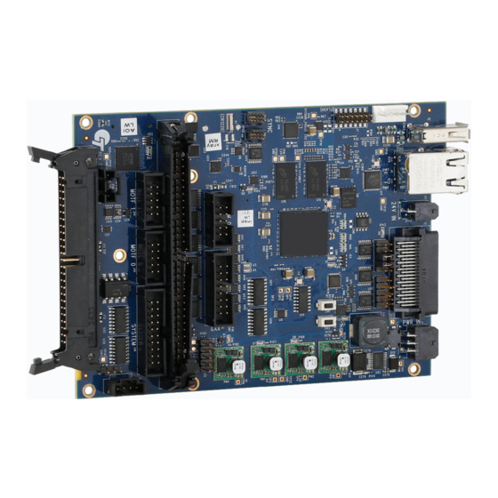
Page 27: Smc, Auxiliary I/O, And High-Power Laser Adapter Assembly
Installation SMC, Auxiliary I/O, and High-power Laser Adapter Assembly 1040-0011 Revision... -
Page 28: System Configuration
Software support is provided through the ScanMaster Designer Editor, the ScanMaster API high-level .NET programming interface, or the ScanMaster Controller XML Software Development Kit. The last is an EC1000 backwards-compatible low-level API that uses standard XML text to configure the SMC and perform scanning jobs. -
Page 29: Smc Interconnection Options
Installation SMC-LSR-01 IPG YLP Laser interface cable SMC-LSR-02 SPI G4 Laser adaptor SMC-LSR-03 Synrad CO2 Laser adaptor SMC-LSR-04 High-power Laser adaptor SMC-LSR-05 Coherent C70 Laser adaptor SMC-IO-01 Auxilliary I/O Module CAT5 Ethernet cable (commercially available) SMC-CMD-01 SMC-CMD-02 SMC-PWR-01 GSBus Adaptor XY2-100 Scanner cable Power cable XY2-100... -
Page 30: Connector Cross-Reference
Pin spacing Board Mating Cable or Board Purpose and Rows by Mfg. Connector Part Connector/Pins Connector Columns Number Novanta Cable 712- 808611 Input power 3mm: 2 X 3 Molex 43045-0602 Molex Part Number 43025-0600 Contact Novanta Lightning 0.050”: 2 X Molex... -
Page 31: Smc Module Connector Pinouts
Mfg. Connector Part Connector/Pins Connector Columns Number XY2-100 Connector XY2-100 0.1”: 2 X 8 30316-6002HB Novanta Cable D10578 TE Connectivity 1- 102387-2 AUX I/O 0.1”: 2 X 32 N3764-6302RB Pins TE Connectivity 6- 87756-8 MOTF1 0.1”: 2 X 5 30310-6002HB... -
Page 32: Power Signal Pinouts (Connectors J1 And J3)
Installation 4.5.1 Power Signal Pinouts (Connectors J1 and J3) The following figure contains the pinout drawing for Connector J1 and Connector J3 (Power Signals). The differential voltage between V+ and V- must be in the range of 15 – 48V. The +24V input is optional and is designed to conveniently supply digital I/O optical isolators on the Auxiliary I/O board. -
Page 33: Recommended Power Supply Connections
Installation Cable SMC-PWR-01 or equivalent 15V – 48V Power Supply BLACK GREEN CHASSIS WHITE NOTE: The Scan-head Power Supply Common must be connected to the SMC V- signal to avoid damage to the SMC or Scan-head interface circuitry +/- 15(24)V XY2-100 To Scan-head Scan-head... -
Page 34: Serial Rs-232 Signal Pinouts (Connector J10)
Installation Connector J3 (+24 Signal) Signal Descriptions Pins 1 – 2 +24V Customer optical isolator supply Digital ground reference 4.5.2 Serial RS-232 Signal Pinouts (Connector J10) The following figure contains the pinout drawing for Connector J10 (RS-232). Note: This pinout does not match the 10-pin serial header pinout of all PC motherboards. Connector J10 (RS-232) Pinouts The following table contains a full description of the signal for each pin in the J10 Connector. -
Page 35: Xy2-100 Signal Pinouts (Connector J11)
Installation Connector J10 (RS-232) Signal Descriptions Odd-numbered Pins (1 – 9) Even-numbered Pins (2 – 10) RS232_RX0 RS232_RTS0 Data input from connected device Request to send to connected device RS232_TX0 RS232_CTS0 Data output to connected device Clear to send from connected device VCC5V0 Reserved for future use... -
Page 36: Connector J11 (Xy2-100) Signal Descriptions
Installation Connector J11 (XY2-100) Signal Descriptions Odd-numbered Pins (1 – 15) Even-numbered Pins (2 – 16) XY2_CLK_DN XY2_CLK_DP 2MHz Clock - negative 2MHz Clock - positive XY2_SYNC_DN XY2_SYNC_DP Frame sync - negative Frame sync - positive XY2_X_DN XY2_X_DP X Data - negative X Data - positive XY2_Y_DN XY2_Y_DP... -
Page 37: Auxiliary Signal Pinouts (Connector J13)
Installation 4.5.4 Auxiliary Signal Pinouts (Connector J13) The following figure contains the pinout drawing for Connector J13 (Auxiliary). Note: This connector uses ejectors to facilitate removal of an attached cable or module. Care must be taken during insertion to avoid damaging the ejectors. Connector J13 (Auxiliary) Pinouts The following table contains a full description of the signal for each pin in the J13 Connector. -
Page 38: Connector J13 (Auxiliary) Signal Descriptions
Installation Connector J13 (Auxiliary) Signal Descriptions Odd-numbered Pins (1 – 63) Even-numbered Pins (2 – 64) AUX_START_ISO AUX_RESET_N_ISO A marking job may contain an Causes the card to execute a soft instruction that causes a pause in reset forcing a complete re- execution until this signal is initialization of the firmware. - Page 39 Installation Connector J13 (Auxiliary) Signal Descriptions Odd-numbered Pins (1 – 63) Even-numbered Pins (2 – 64) AUX_BUSY AUX_LASING Asserted when a BeginJob Asserted when marking is in instruction is executed; de- progress. It is de-asserted when an asserted when an EndJob EndJob instruction is executed.
- Page 40 Installation Connector J13 (Auxiliary) Signal Descriptions Odd-numbered Pins (1 – 63) Even-numbered Pins (2 – 64) EXT-VCC5V0 Fused 5 Volts available for logic on Digital ground reference an Auxiliary I/O board AUX_AMOTF1_DP AUX_AMOTF1_DN Secondary mark-on-the-fly encoder Secondary mark-on-the-fly encoder input. Expected to be connected input.
- Page 41 Installation Connector J13 (Auxiliary) Signal Descriptions Odd-numbered Pins (1 – 63) Even-numbered Pins (2 – 64) AUX_STEP1 AUX_DIR1 Step control signal for a Direction control signal for a programmable stepper motor programmable stepper motor +24V Customer-supplied optical isolator Digital ground reference voltage.
-
Page 42: Motf-1 Signal Pinouts (Connector J14)
Installation Connector J13 (Auxiliary) Signal Descriptions Odd-numbered Pins (1 – 63) Even-numbered Pins (2 – 64) AUX_XY2_STAT2 AUX_XY2_INPOS Port 2 XY2-100 Status 2 (reserved) Port 2 XY2-100 In Position Note: Before use with a scan head Note: Before use with a scan head this signal must be signal this signal must be signal conditioned with differential... -
Page 43: Connector J14 (Motf-1) Pinouts
Installation Connector J14 (MOTF-1) Pinouts The following table contains a full description of the signal for each pin in the J14 Connector. These signals are replicated from the Auxiliary I/O connector J13. Connector J14 (MOTF-1) Signal Descriptions Odd-numbered Pins (1 –9) Even-numbered Pins (2 –... -
Page 44: Motf-0 Signal Pinouts (Connector J15)
Installation Connector J14 (MOTF-1) Signal Descriptions Odd-numbered Pins (1 –9) Even-numbered Pins (2 – 10) EXT_VCC5V0 5 Volts available for encoder Digital ground reference power AUX_GPO2 CHASSIS A marking job may contain an Expected to be tied to earth ground instruction that causes a pause in execution until this signal is asserted by external equipment. -
Page 45: Control Signal Pinouts (Connector J16)
Installation Connector J15 (MOTF-0) Signal Descriptions Odd-numbered Pins (1 –9) Even-numbered Pins (2 – 10) AUX_BMOTF0_DP AUX_BMOTF0_DN Primary mark-on-the-fly encoder Primary mark-on-the-fly encoder input. Expected to be connected input. Expected to be connected to an RS-485 positive “B” phase to an RS-485 negative “B” phase differential signal or a 5V TTL differential signal. -
Page 46: Connector J16 (Control) Pinouts
Installation Connector J16 (Control) Pinouts The following table contains a full description of the signal for each pin in the J16 Connector. Connector J16 (Control) Signal Descriptions Odd-numbered Pins (1 – 19) Even-numbered Pins (2 – 20) AUX_START_ISO AUX_RESET_N_ISO A marking job may contain an Causes the SMC to execute a soft instruction that causes a pause in reset forcing a complete re-... - Page 47 Installation Connector J16 (Control) Signal Descriptions Odd-numbered Pins (1 – 19) Even-numbered Pins (2 – 20) AUX_ABORT_ISO AUX_COM_ISO Causes the job execution control Optical isolator common for logic to abort the current job and signals AUX_START_ISO, return to an idle state. This signal AUX_RESET_N_ISO, and must be activated using the AUX_ABORT_ISO...
-
Page 48: External Trigger Pinouts (Connector J17)
Installation Connector J16 (Control) Signal Descriptions Odd-numbered Pins (1 – 19) Even-numbered Pins (2 – 20) AUX_BUSY AUX_LASING Asserted when a BeginJob Asserted when marking is in instruction is executed; de- progress. asserted when an EndJob instruction is executed. AUX_GPO1 AUX_GPO2 A marking job instruction may A marking job instruction may... -
Page 49: Laser Signal Pinouts (Connector J18)
Installation The following table contains a full description of the signal for each pin in the J17 Connector. Connector J17 (External Trigger) Signal Descriptions Pins 1 – 4 EXT_VCC5V0 5 Volts available for logic on customer board Digital ground reference START A marking job may contain an instruction that pauses execution until this signal is asserted by external equipment. -
Page 50: Connector J18 (Laser) Pinouts
Installation Connector J18 (Laser) Pinouts The following table contains a full description of the signal for each pin in the J18 Connector. Connector J18 (Laser) Signal Descriptions Odd-numbered Pins (1 – 49) Even-numbered Pins (2 – 50) LASER_DATA0 Digital data representing a laser Digital ground reference power setting LASER_DATA1... - Page 51 Installation Connector J18 (Laser) Signal Descriptions Odd-numbered Pins (1 – 49) Even-numbered Pins (2 – 50) LASER_DATA4 LASER_ENABLE Digital data representing a laser Asserted a programmable time prior power setting to a sequence of mark instructions; de-asserted after a programmable period of laser inactivity.
- Page 52 Installation Connector J18 (Laser) Signal Descriptions Odd-numbered Pins (1 – 49) Even-numbered Pins (2 – 50) LASER_STAT6_ISO_RETURN LASER_STAT45COM_ISO Current return for LASER_STAT6 Optical isolator common for signals LASER_STAT4_ISO_ADC0 and LASER_STAT5_ISO_ADC1 SPI_MISO SPI_MOSI Reserved for future use Reserved for future use SPI_SS_LASER0_N SPI_CLK Reserved for future use...
-
Page 53: E-Stop (Connector Jp6)
Installation Connector J18 (Laser) Signal Descriptions Odd-numbered Pins (1 – 49) Even-numbered Pins (2 – 50) ESTOP_LOOP ESTOP2_LOOP Used to access laser interlock Used to access laser interlock Notes On Interlock Behavior: LASER_STAT[2 – 0]_ISO can be configured by the software to generate an interlock exception if an inappropriate signal level is received. -
Page 54: Connector Jp6 (E-Stop) Pinouts
Installation Connector JP6 (E-STOP) Pinouts The following table contains a full description of the signal for each pin in the JP6 Connector. Connector JP6 (E-STOP) Signal Descriptions Pins 1 – 4 EXT_VCC5V0 SMC supplied +5V source ESTOP_LOOP Signal ESTOP_LOOP on J18 pins 20 and 49 Digital ground reference ESTOP2_LOOP Signal ESTOP2_LOOP on J18 pins 24 and 50... -
Page 55: Usb Port 1 Pinouts (Connector J5)
Installation 4.5.11 USB Port 1 Pinouts (Connector J5) The following figure contains the pinout drawing for the standard USB Port 1 Connector J5. Connector J5 (USB Port 1 Pinouts) The following table contains a full description of the signal for each pin in the J5 Connector. Connector J5 (USB Port 1 Header) Signal Descriptions Pins 1 –... -
Page 56: Usb Port 2 Header Pinouts (Connector J6)
Installation Connector J5 (USB Port 1 Header) Signal Descriptions Pins 1 – 4 Standard USB Type A Ground 4.5.12 USB Port 2 Header Pinouts (Connector J6) The following figure contains the pinout drawing for the optional Connector J6 (USB Port 2 Header). Connector J6 (USB Port 2 Header) Pinouts The following table contains a full description of the signal for each pin in the J6 Connector. -
Page 57: Signal Conditioning
Installation Connector J6 (USB Port 2 Header) Signal Descriptions Pins 1 – 5 USBB_PWR Standard USB Port 2 power pin USBB_DM Standard USB Port 2 data minus USBB_DP Standard USB Port 2 data plus Standard USB Port 2 Ground CHASSIS Expected to be tied to earth ground SIGNAL CONDITIONING The following figures illustrate the signal conditioning for the various signal groups of the SM. -
Page 58: High-Speed Laser Synchronization - J18
Installation 4.6.2 High-speed Laser Synchronization – J18 J18 Signals LASER_STAT6_ISO Internal Laser Status 6 Signal (For high speed laser sync) LASER_STAT6_ISO_RETURN Signal Conditioning for High-speed Laser Synchronization (J18) 4.6.3 Laser Status 0-5 Signals – J18 J18 Signals LASER_STAT{0-3}_ISO Internal Laser LASER_STAT4_ISO_ADC0 Status {0-5} Signals LASER_STAT5_ISO_ADC1... -
Page 59: System Control Inputs - J13 And J16
Installation 4.6.5 System Control Inputs – J13 and J16 J13 & J16 Signals AUX_START_ISO Internal System AUX_RESET_N_ISO Control Signals AUX_ABORT_ISO AUX_COM_ISO 4.7K Signal Conditioning for System Control Inputs (J13 and J16) 4.6.6 START Input – J17 and J15 Signal Conditioning for START Input (J17 and J15) 1040-0011 Revision... -
Page 60: System Control Outputs And General Purpose Outputs - J13 And J16
Installation 4.6.7 System Control Outputs and General Purpose Outputs – J13 and J16 From user connect or J3 +24V J13 & J16 Signals AUX_ERROR_REA DY _N AUX_JOBA CTI VE Internal System Cont rol Signals AUX_BUSY AUX_LA SING AUX_GPO {1-4} Signal Conditioning for System Control and General O/P (J13 & J16) Note: These outputs are pulled up to +5V through a diode for convenience of driving lightly loaded TTL devices. -
Page 61: Laser Control Outputs - J18
Installation Internal System Control Signals Expected Usage of Digital Outputs 4.6.8 Laser Control Outputs – J18 J18 Signals Global Enable LASER_DATA{0-7} LASER_DATALATCH LASER_ENABLE Internal System Control Signals LASER_MOD{1-3} LASER_GATE LASER_POINTER Tri-state on power-up until configured Signal Conditioning for Laser Control Outputs (J18) 1040-0011 Revision... -
Page 62: Auxiliary Xy2-100 Signals - J13
Installation 4.6.9 Auxiliary XY2-100 Signals – J13 +3.3V J13 Signals Global Enable AUX_XY2_CLK AUX_XY2_SYNC Internal System AUX_XY2_X Control Signals AUX_XY2_Y AUX_XY2_Z J13 Signals AUX_XY2_STAT Internal System AUX_XY2_STAT2 Control Signals AUX_XY2_INPOS Tri-state on power-up until configured Signal Conditioning for Auxiliary XY2-100 Signals (J13) 1040-0011 Revision... -
Page 63: Appendix A - Smc-Io-01 Auxiliary I/Omodule
Appendix A - SMC-IO-01 Auxiliary I/O Module 5 APPENDIX A - SMC-IO-01 AUXILIARY I/O MODULE INTRODUCTION The Auxiliary I/O module provides additional digital I/O capability to the SMC, and exposes the SMC digital signals using 3.5mm Phoenix Contact industrial-automation-style connectors. The Auxiliary I/O module can be attached to the SMC main module as a plug-in daughter card or via ribbon cables. -
Page 64: Mechanical Layout
Appendix A - SMC-IO-01 Auxiliary I/O Module MECHANICAL LAYOUT Auxiliary I/O module outline drawing Regardless of the product family (Lightning II or ProSeries 2), the mechanical installation of the 3-Axis Scanning System should proceed as described in the following pages. CONNECTORS 5.3.1 J3 AND J4 - XY2 - 100 PORTS Port 1 is the same port as on the XY2-100 Connector of the SMC Main Module. -
Page 65: J11 - Rs - 485 Communications
Appendix A - SMC-IO-01 Auxiliary I/O Module J3 XY2-100 Port 1 and J4 XY2-100 Port 2 5.3.2 J11 – RS - 485 Communications This connector is intended to provide communications to smart stepper motor controllers. The pins on Connector J11 (RS-485 Communications) are described below. 1040-0011 Revision... -
Page 66: J10 - Rs - 232 Communications
Appendix A - SMC-IO-01 Auxiliary I/O Module J11 RS-485 Communications 5.3.3 J10 – RS – 232 Communications This DB-9F connector provides general purpose RS-232 access to the SMC. Although it presents as a device COM port (DB-9F), in Revision C of the I/O board, it is configured as a Host COM port as shown in the diagram below. -
Page 67: J15 And J16 - Motf 0 And Motf
Appendix A - SMC-IO-01 Auxiliary I/O Module J10 RS-232 Communications 5.3.4 J15 and J16 – MOTF 0 And MOTF 1 The MOTF connectors expose the same signals as the MOTF-0 and MOTF-1 connectors on the SMC Main Module. Refer to the following for descriptions of these signals: •... -
Page 68: J6 And J8 - Extended Digital Inputs
Appendix A - SMC-IO-01 Auxiliary I/O Module J15 MOTF Port 0 (X) and J16 MOTF Port 1 (Y) 5.3.5 J6 and J8 – Extended Digital Inputs These inputs are 5- to 24V-compatible optically isolated inputs. The inputs can be sourcing or sinking depending on the connection of the COM input. - Page 69 Appendix A - SMC-IO-01 Auxiliary I/O Module Note: +24V should not be left floating. If a 24V supply is not available, then connect EXT_VCC5V0 to +24V through a diode: J6 Extended Inputs Bank 0 J8 Extended Inputs Bank 1 1040-0011 Revision...
-
Page 70: J7 And J9 - Extended Digital Outputs
Appendix A - SMC-IO-01 Auxiliary I/O Module J6 Signals Internal EXTAUXIN {0-7} EXTAUXIN{0-7} J6 pins 5-12 Signals AUX_GPICOM0_ISO J6 pin 2 4.7K J8 Signals Internal EXTAUXIN {8-15} EXTAUXIN{8-15} J8 pins 5-12 Signals AUX_GPICOM1_ISO J8 pin 2 4.7K Extended Inputs Signal Conditioning 5.3.6 J7 and J9 –... - Page 71 Appendix A - SMC-IO-01 Auxiliary I/O Module J7 Extended Outputs Bank 0 J9 Extended Outputs Bank 1 1040-0011 Revision...
-
Page 72: J13 And J14 - External Motor Control
Appendix A - SMC-IO-01 Auxiliary I/O Module +24V +24V J7 Pin2 and J9 pin2 J7 & J9 Signals EXTAUXOUT{0-7} J7 pins 4-11 EXTAUXOUT{8-15} J9 pins 4-11 X 16 Internal System Control Signals GND J7 pin 1 and J9 pin 1 Extended Outputs Signal Conditioning 5.3.7 J13 and J14 –... -
Page 73: J5 And J12 - System Control Inputs And Outputs
Appendix A - SMC-IO-01 Auxiliary I/O Module J13 and J14 External Motor Control Port 0 and Port 1 5.3.8 J5 and J12 - System Control Inputs and Outputs These signals are the same as those for the Control Signals on Connector J16 of the SMC Main Module. -
Page 74: J12 System Control Outputs
Appendix A - SMC-IO-01 Auxiliary I/O Module J12 System Control Outputs Note: The silkscreen on Rev C of this module incorrectly labels AUX_GPO[1-4] as GPO[0-3]. This is fixed in later revisions. 1040-0011 Revision... -
Page 75: Appendix B - Smc-Lsr-01 Ipg Laser Adapter
Appendix B - SMC-LSR-01 IPG Laser Adapter 6 APPENDIX B - SMC-LSR-01 IPG LASER ADAPTER INTRODUCTION The IPG Laser Adapter provides convenient connectivity from the SMC Laser Connector (J18) to the 25-pin D-SUB Connector used by IPG Laser on their low-power YLP models. The IPG Laser Adapter has the following features: •... -
Page 76: Connectors
Appendix B - SMC-LSR-01 IPG Laser Adapter CONNECTORS 6.3.1 Laser Signal Mappings SMC and IPG signals and connector pin mappings are identified in the following table. 25-Pin IPG YLP IPG YLP Color SMC Signal D-Sub (Type D) (Type E) LASER_DATA0 Ground Ground LASER_DATA1... -
Page 77: Smc-Lsr-01 Usage With Ipg Ylp-Hp Type B Interface
Appendix B - SMC-LSR-01 IPG Laser Adapter Modulation Digital In Return Reserved ESTOP_LOOP EMstop AuxOFF LASER_STAT2_ISO ALARM2 ALARM2 Digital In Digital In LASER_STAT4_ISO_ADC0 Reserved Reserved Digital Out Digital Out LASER_STAT3_ISO Reserved Reserved ESTOP2_LOOP Reserved Reserved Digital In Digital In LASER_STAT5_ISO_ADC1 Reserved Reserved IPG Laser Adapter Cable Signal Mappings... -
Page 78: Modifications Of Smc-Lsr-01 For Ipg Ylp-Hp Type B Connection
Appendix B - SMC-LSR-01 IPG Laser Adapter Modifications of SMC-LSR-01 for IPG YLP-HP Type B Connection IPG YLP-HP 25-Pin D- Color SMC Signal SUB Pin (Type B) LASER_DATA0 Ground LASER_DATA1 LASER_STAT03COM_ISO_PIN Reserved Cut this wire LASER_DATA2 LASER_STAT1_ISO ALARM0 LASER_DATA3 PTR_VCC5V0 LASER_DATA4 LASER_ENABLE LASER_DATA5... -
Page 79: Connector Jp6 (E-Stop) Pinouts
Appendix B - SMC-LSR-01 IPG Laser Adapter Note: Connect the cut GRN wire attached to the 25P D-SUB pin 13 to the cut YEL wire attached to the 50P connector pin 24. E-STOP connector J6 should be used to access the laser AStop (ESTOP_LOOP) and Reset (ESTOP2_LOOP) signals for laser enabling and fault reset. -
Page 80: Custom Cable Pinouts For Ipg Ylp-Hp Type B Interface
Appendix B - SMC-LSR-01 IPG Laser Adapter Custom Cable Pinouts for IPG YLP-HP Type B Interface SMC-LSR-01 25P D- Custom cable 25-Pin IPG YLP-HP (Type SMC Signal Sub Pin D-Sub Pin LASER_DATA0 Ground LASER_DATA1 DO NOT CONNECT Reserved LASER_DATA2 LASER_STAT1_ISO ALARM0 LASER_DATA3 PTR_VCC5V0... - Page 81 Appendix B - SMC-LSR-01 IPG Laser Adapter DO NOT CONNECT Reserved LASER_STAT3_ISO ALARM3 DO NOT CONNECT Reserved ESTOP2_LOOP Reset Note: SMC connector JP6 provides PLC access to the laser AStop (ESTOP-LOOP) and Reset (ESTOP2- LOOP) signals. 1040-0011 Revision...
-
Page 82: Appendix C - Smc-Lsr-02 Spi Laser Adapter
Appendix C – SMC-LSR-02 SPI Laser Adapter 7 APPENDIX C – SMC-LSR-02 SPI LASER ADAPTER INTRODUCTION The SPI Laser Adapter provides convenient connectivity from the SMC Laser Connector (J18) to the 68-pin High-density Connector used by SPI Lasers on their G3 and G4 models. The SPI Laser Adapter has the following features: •... -
Page 83: Mechanical Layout
Appendix C – SMC-LSR-02 SPI Laser Adapter MECHANICAL LAYOUT SPI Laser Adapter Mechanical Layout CONNECTORS 7.3.1 J2 SPI Laser Connector SMC signals are identified in the yellow off-page symbols. Signals that are labeled but not connected to an off-page symbol are not used in this design. 1040-0011 Revision... -
Page 84: J3 E-Stop Connector
Appendix C – SMC-LSR-02 SPI Laser Adapter SPI Laser Connector Signal Assignments 7.3.2 J3 E-STOP Connector The E-STOP Connector provides access to the SPI LASER_DISABLE_H signal. With an appropriate jumper inserted, the laser can be enabled without external interlock circuitry. The ESTOP_LOOP signal is also connected to the SMC through the J18 connector on the SMC. -
Page 85: E-Stop Connector Signal Assignments
Appendix C – SMC-LSR-02 SPI Laser Adapter E-STOP Connector Signal Assignments 1040-0011 Revision... -
Page 86: Appendix D - Smc-Lrs-04 High-Power Laser Adapter
Appendix D - SMC-LRS-04 High-power Laser Adapter 8 APPENDIX D - SMC-LRS-04 HIGH-POWER LASER ADAPTER INTRODUCTION The High-power Laser Adapter provides convenient connectivity from the SMC Laser Connector (J18) to industrial automation-style connectors. A subset of the SMC digital laser control signals has been reconditioned to drive 24V circuitry, which is typically seen in high-power fiber lasers from IPG and in differential drive circuitry for CO2 lasers from Coherent. -
Page 87: Mechanical Layout
Appendix D - SMC-LRS-04 High-power Laser Adapter MECHANICAL LAYOUT High-Power laser adapter mechanical layout CONNECTORS The laser signals from the SMC High-power Laser Adapter are exposed on three connectors: two 12- pin Phoenix Contact strips and one BNC connector. Note: Pins 6, 7, and 8 are incorrectly labeled on Rev C of the adapter module. The following table has the correct pin assignments. -
Page 88: J2 - Laser Signal Set
Appendix D - SMC-LRS-04 High-power Laser Adapter 8.3.1 J2 - Laser Signal Set 1 Laser Signal Set 1 Pins (1 – 12) +24V This pin provides external voltage to the high-voltage digital signal drivers. It is also connected to the SMC 24V connector J3. LASER_ENABLE_BUF High-voltage buffered version of the SMC LASER_ENABLE signal LASER_GATE_BUF... -
Page 89: J3 - Laser Signal Set
Appendix D - SMC-LRS-04 High-power Laser Adapter Pins (1 – 12) Digital ground reference 8.3.2 J3 - Laser Signal Set 2 Laser Signal Set 2 Pins (1 –12) +24V This pin provides external voltage to the high-voltage digital signal drivers. It is also connected to the SMC 24V connector J3. -
Page 90: J5 Bnc Laser Modulation Output
Appendix D - SMC-LRS-04 High-power Laser Adapter Pins (1 –12) LASER_SYNC_DN RS-485 differential negative input of a laser sync signal Digital ground reference 8.3.3 J5 - BNC Laser Modulation Output J5 BNC Laser Modulation Output LOCAL LASER MODULATION CONTROL This High-power Laser Adapter provides support for generating a laser modulation signal without the SMC being involved. -
Page 91: Selective Pull-Up/Pull-Down Of Control Signals
Appendix D - SMC-LRS-04 High-power Laser Adapter +24V LASER_ENABLE_BUF LASER_GATE_BUF LASER_MOD1_BUF LASER_POINTER_BUF Circuitry supplied by the user LASER_ANALOG1 LASER_ANALOG1_GATED LASER_LOCAL_MOD_SUPPLY LASER_LOCAL_MOD_CONTROL LASER_LOCAL_ENB_N Remote Modulation Control Configuration SELECTIVE PULL-UP/PULL-DOWN OF CONTROL SIGNALS By default, the main laser control signals are actively pulled down to ground through 20K resistors as shown in the following figure. -
Page 92: Appendix E - Smc-Lsr-05 Coherent C70 Laser Adapter
Appendix E - SMC-LSR-05 Coherent C70 Laser Adapter 9 APPENDIX E - SMC-LSR-05 COHERENT C70 LASER ADAPTER INTRODUCTION The Coherent C70 Laser Adapter provides convenient connectivity from the SMC Laser Connector (J18) to industrial automation-style connectors and to the RJ45 connector used with the Coherent model C70 CO2 laser. -
Page 93: Mechanical Layout
Appendix E - SMC-LSR-05 Coherent C70 Laser Adapter MECHANICAL LAYOUT Coherent C70 Laser Adapter Mechanical Layout CONNECTORS The laser signals from the Coherent C70 Laser Adapter are exposed on two connectors: one 8-pin RJ45 connector, and one 12-pin 3.5mm Phoenix Contact strip 9.3.1 J5 - RJ-45 Laser Control Signals RJ-45 Laser Control Signals Pins (1 –... -
Page 94: J2 - Auxiliary Laser Control Signals
Appendix E - SMC-LSR-05 Coherent C70 Laser Adapter Pins (1 – 8) +15V_IN +15V supply voltage from the laser LASER_OK_IN Laser OK signal from the laser TEMP_OK_IN Temperature OK signal from the laser VOLTAGE_OK_IN Voltage OK signal from the laser Digital ground reference LASER_ENB_OUT Laser enable... -
Page 95: Local Laser Modulation Control
Appendix E - SMC-LSR-05 Coherent C70 Laser Adapter Pins (1 –12) VOLTAGE_OK_BUF 24V capable buffered version of the VOLTAGE_OK_IN signal from J5 Digital ground reference CHASSIS Chassis ground reference LASER_MOD_OUT Laser modulation signal. Same as J5 pin 1 LASER_LOCAL_MOD_SUPPLY Voltage source for external circuitry that control local modulation behavior LASER_LOCAL_MOD_CONTROL Analog input control signal for regulating the duty-cycle of a local 10KHz modulation source... -
Page 96: Remote Modulation Control Configuration
Appendix E - SMC-LSR-05 Coherent C70 Laser Adapter LASER_ENABLE_BUF LASER_OK_BUF TEMP_OK_BUF VOLTAGE_OK_BUF Circuitry supplied by the user CHASSIS LASER_MOD_OUT LASER_LOCAL_MOD_SUPPLY LASER_LOCAL_MOD_CONTROL LASER_LOCAL_ENB_N Remote Modulation Control Configuration Pull-up/Pull-down of Control Signals to support disabling the assertion state of the laser signals on power-up, there are four jumpers that can be applied to pull-up these signals when they are not being actively driven as is the case during a power-up cycle. -
Page 97: Appendix F - Xy2-100 Protocol Interface
10 APPENDIX F - XY2-100 PROTOCOL INTERFACE The XY2-100 Serial Link (also known as Serial Link 1 and XYZ-100) is a synchronous TIA/EIA-422-B differential digital interface for communication of three 16-bit position words and a single 16-bit status word for 2- and 3-Axis servo applications 10.1 CONNECTIONS AND SIGNAL DESCRIPTIONS Typically, a female connector is used by a position data receiver such as a scan head, and may optionally include differential power as shown in below table. -
Page 98: Clock
Appendix F - XY2-100 Protocol Interface 10.2 CLOCK The Clock is transmitted by the position data generator, 20 cycles per frame. Its nominal frequency is 2MHz. 10.3 SYNC The frame Sync is a single logical "0" pulse, once per frame, transmitted by the position data generator one clock cycle prior to the first bit of the frame. -
Page 99: Status Data
0 1 0 Reserved 0 1 1 Test (reserved) 20-bit Novanta Extended Precision data follows (odd parity, 1 x x reserved) 10.5 STATUS DATA The Status Data is a 20-bit serial data stream consisting of a 3-bit control code, one 16-bit status word, and a parity bit (even parity). - Page 100 Appendix F - XY2-100 Protocol Interface Status Data Formats 2-axis status 3-axis status In-field X Tracking Error X Position Acknowledge Y Position Acknowledge Y Error Status (Y Servo Ready) Y Temperature Status Y Tracking Error Power Status Z Error Status (Z Servo Ready) Temperature Status Z Temperature Status In-field...
-
Page 101: Index
Index 11 INDEX Automation interfaces, 12 ProSeries 2, 8 Auxiliary I/O Module Pinouts Revision history, 4 J12 Connector Pinouts, 63 Serial Link 1. See XY2-100 Protocol Interface J5 Connector Pinouts, 63 Signal Conditioning, 47 Cables, 21 Auxilliary XY2-100 Signals (J13), 52 Cleaning, 88 General Purpose Inputs (J13 and J16), 48 Connectors, 21... - Page 102 This page is left blank intentionally 1040-0011 Revision...
- Page 103 Engineered by Cambridge Technology, part of Novanta Novanta Headquarters, Bedford, USA Phone: +1-781-266-5700 Email: photonics@novanta.com 1040-0011 Revision A April 2022 © 2022, Novanta Corporation. All rights reserved.
Need help?
Do you have a question about the ScanMaster and is the answer not in the manual?
Questions and answers