Sign In
Upload
Manuals
Brands
Nordson EFD Manuals
Controller
2+2-XCH-V3
Nordson EFD 2+2-XCH-V3 Manuals
Manuals and User Guides for Nordson EFD 2+2-XCH-V3. We have
1
Nordson EFD 2+2-XCH-V3 manual available for free PDF download: Operating Manual
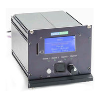
Nordson EFD 2+2-XCH-V3 Operating Manual (84 pages)
PICO Controller
Brand:
Nordson EFD
| Category:
Controller
| Size: 6 MB
Table of Contents
Table of Contents
3
Contents
3
Introduction
5
Product Description
5
How the V3 Controller Is Different from the V2 Controller
6
Intended Use
6
Applicability of this Manual
6
Nordson EFD Product Safety Statement
7
Specifications
8
Standards
9
Operating Features
10
Front Panel Components
10
Back Panel Components
11
Installation
12
Unpack and Inspect
12
Make the System Connections
12
Connector Pin Assignments and Signal Levels
13
Power Supply Socket Pins
13
CAN Interface D-Subconnector Pins
13
Channels 1-4 D-Subconnector Pins
13
Installation Example
15
Setup
16
Design and Interfaces
16
Signal Level Sources
17
Device-Internal Potential
18
External Potential
18
Output Impulses
19
Fieldbus Communication Via CAN Interface
21
Network Installation
21
The CAN Data Telegram
22
Structure of the 11-Bit Identifier
22
Structure of Data Bytes 0-7
22
CAN Communication Command Examples
24
About Local Service Flags
28
About the Transaction Number (TAN)
28
PICO Controller Menu Structure
29
PICO Controller Display
30
PICO Controller Operating Controls
31
Parameters and Value Ranges
32
PICO Controller Menu Schematic
34
Control Programs
38
Program Cycles, Program Files, and Factory Settings
38
Characteristics of a Control Program
40
Program Examples
41
Operation
44
Checklist for Initial Operation
44
Changing the Temperature Setting Range
45
Purging a Valve
45
Changing a Container
46
EMERGENCY off Functionality
47
Service
48
Maintenance
48
Cleaning
48
Replacing the Battery
49
Part Numbers
49
Replacement Parts
49
Troubleshooting
50
Technical Data
52
Circuit Diagram (Device Internal Potential)
52
Circuit Diagram (External Potential)
53
PICO Controller Dimensions
54
Product Description
55
Applicability of this Supplement
56
PROFIBUS Communicator Specifications
57
PROFIBUS Communicator Standards
57
PROFIBUS Communicator Operating Features
58
PROFIBUS Communicator Installation
59
Inspect Kit Components
59
Make the System Connections
59
Installation Examples
60
PROFIBUS Interface D-Subconnector Pins
63
PROFIBUS Communicator Status LED Indications
63
PROFIBUS Communicator Setup
64
Applicability of this Section
64
Parameterization of the PICO Controller Via the PROFIBUS Communicator
64
Organization of the Bus System/Parameterization
64
Integrating the Communicator in a Siemens S7 Project
65
Siemens S7 Project Description
70
Overview of the Applied Data and Function Blocks
70
Low-Level Drivers FB15 and FB16
71
Function Block FB20
72
High-Level Driver FB19
74
Important Information about PLC Blocks
75
Using FB20 to Write a Parameter
75
Using FB20 to Read a Parameter
76
Using FB20 to Initiate Dispensing
77
Using FB19 to Simultaneously Write Multiple Parameters
78
Value Codes and Admissible Value Ranges
79
Essential Addresses and Address Content
80
PROFIBUS Communicator Part Numbers
82
PROFIBUS Communicator Replacement Parts
82
PROFIBUS Communicator Troubleshooting
82
Advertisement
Advertisement
Related Products
Nordson EFD PICO Controller 2+2 CH-V2 Series
Nordson EFD PICO Controller 2+2-2CH-V2
Nordson EFD PICO Controller 2+2-4CH-V2
Nordson EFD 2K Pneumatic Dispense Gun
Nordson EFD 7015899
Nordson EFD 7015900
Nordson EFD Liquidyn V10D
Nordson EFD PICO Touch
Nordson EFD PICO Touch Series
Nordson EFD PICO Touch-XP
Nordson EFD Categories
Controller
Control Unit
Dispenser
Industrial Equipment
Temperature Controller
More Nordson EFD Manuals
Login
Sign In
OR
Sign in with Facebook
Sign in with Google
Upload manual
Upload from disk
Upload from URL