Sign In
Upload
Manuals
Brands
NKT Photonics Manuals
Measuring Instruments
SuperK FIANIUM FIU-15
NKT Photonics SuperK FIANIUM FIU-15 Laser Manuals
Manuals and User Guides for NKT Photonics SuperK FIANIUM FIU-15 Laser. We have
1
NKT Photonics SuperK FIANIUM FIU-15 Laser manual available for free PDF download: Product Manual
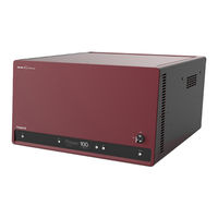
NKT Photonics SuperK FIANIUM FIU-15 Product Manual (113 pages)
White Light Laser
Brand:
NKT Photonics
| Category:
Measuring Instruments
| Size: 14.17 MB
Table of Contents
Guide Overview
3
Table of Contents
5
Tables
11
Figures
13
Procedures
15
Superk Fianium Description
17
1 Laser Description
19
Terminology
19
Front Panel Controls
19
Figure 1 Superk FIANIUM General View
19
Control
20
Temperature Regulation
20
Accessories
20
Optical Output
20
Supercontinuum
20
Optical Specifications
20
Table 1 Optical Specifications
20
Spectral Output
21
Collimator
21
Figure 2 Supercontinuum Output of the Laser
21
Figure 3 Superk FIANIUM Collimator
21
Beam Diameter
22
Factory Test Report
22
Output Polarization
22
Polarization Ring
22
Table 2: Beam Diameter (1/E2 Limit) after Collimator for Three Wavelengths
22
Pulse Picker - VRR (Optional)
23
Repetition Rates
23
Table 3 Frequency Versus VRR Factor
23
Figure 4 Polarization Ring Mounted on a Collimator
23
Using VRR
24
Output Power
24
Reflection Monitor
24
Front Panel Controls
25
Power Button
25
Status Button
25
Display Panel
25
Power down Button
25
Power up Button
25
Key Switch
25
Figure 5 Front Panel Controls
25
Emission Button
26
Rear Panel
26
Figure 6 Rear Panel Features and Connectors
26
Input and Output BNC Ports
28
Pre-VRR Ports
28
Figure 7 NIM Pulse Output
28
Figure 8 Pulse Output
28
Post-VRR Ports
29
External Feedback
29
Booster ON/OFF
29
Connecting a PC
30
USB Port
30
RS-232 Serial Port
30
Ethernet Port
31
Table 4 RS-232 Serial Port Settings
31
Configuration and Operation Overview
32
CONTROL Application
32
Advanced Laser Control
32
Key Switch and Interlock Safety
32
External Bus
33
Status Leds
34
Table 5 Status Leds
34
Figure 9 Superk FIANIUM Rear Panel Status Leds
34
Chassis Labels
35
Table 6 Chassis Labels
35
Figure 10 Rear Panel Labels
35
Installing the Laser
37
2 Mechanical Installation
39
General Installation
39
Installing the Laser Chassis
40
Table 7 Air Flow Considerations
40
Figure 11 Superk FIANIUM Installation
40
3 Connecting the Laser
41
Connecting the Safety Interlock
42
Interlock Operation
42
Figure 12 Interlock Connected to a Door Switch - Laser Armed
42
Figure 13 Interlock Connected to a Door Switch - Laser SHUTDOWN
43
Safety Door Switch
43
Connecting Power
44
Table 8 Interlock Circuit Specifications
44
Procedure 1 Connecting the Door Interlock Circuit
44
Procedure 2 Connecting Power
44
Connecting the Optical Output
45
Back Reflection
45
Installing the Collimator
45
Connecting Accessories with the External Bus
46
External Bus
46
Figure 14 Inserting the Collimator into a Holder
46
Figure 15 Collimator Inserted into a Superk Accessory Receptacle
46
Figure 16 Collimator Inserted in a Holder Receptacle
46
Connecting the External Bus
47
Figure 17 Bus Defeater
47
Table 9 External Bus Port - Connecting Accessories
47
Figure 18 External Bus Circuit - with no Accessories Used
48
Figure 19 External Bus Circuit - with Multiple Accessories in a Daisy Chain
48
Connecting Synchronization Ports
49
Example Synchronization Circuit
49
Figure 20 Synchronization Ports with Output Signals
49
Table 10 Pulse Synchronization Signals
49
Figure 21 Example NIM Pulse Circuit
50
Gate out
50
Pulse out
50
Table 11 Gate out Port Specification
50
Figure 22 Pulse (NIM) Trigger Delay Control
51
NIM Pulse
51
Table 12 Pulse out Ports Specification
51
Table 13 NIM Pulse Ports Specification
51
4 Connecting External Control
53
External Feedback
53
Feedback Circuit
53
Table 14 External Feedback Port and Cabling Parameters
53
Booster ON/OFF
54
Table 15 Booster Port and Cabling Parameters
54
Figure 23 Output Control Trigger Vs Optical Output Rise
54
Operating the Laser
55
5 Front Panel Controls
57
Overview
57
Table 16 Panel Buttons and Keyswitch
57
Figure 24 Front Panel Buttons and Display
57
Figure 25 Keyswitch Control - Set to Armed
57
Display
58
Viewing Display
58
Dimming
58
Operation Page
58
Table 17 Display Pages
58
Table 18 Emission Status
59
Figure 26 Operation Page
59
Connected Modules Page
60
Figure 27 Connected Modules Page
60
Error Page
61
Clearing the Error Message
61
Error Identification
61
Notification Page
61
Figure 28 Error Page
61
Clearing the Notification Page
62
Operating the Laser from the Front Panel
62
Front Panel Operations
62
Powering on and off the Laser
62
Table 19 Front Panel Operations
62
Figure 29 Notifications Page - Laser Calibration
62
Procedure 4 Turning on the Laser
62
Adjust the Power
63
Figure 30 Boot Screen
63
Procedure 5 Turning off the Laser
63
Arming the Laser
64
Figure 31 Power Adjusted to 0% before Enabling Emission
64
Figure 32 Power Adjusted to 100% with Emission Enabled
64
Figure 33 Laser Is Armed
64
Procedure 6 Arming the Laser
64
Enable Emission
65
Disable Emission
65
Figure 34 Emission Enabled
65
6 Using CONTROL to Turn on the Laser
67
CONTROL Software
67
Installing the Software
67
Connecting the Laser to a CONTROL PC
67
Procedure 9 Connecting CONTROL to the Laser
68
Controlling the Laser Emissions
69
Preparation
69
Safety
69
Errors
70
Turning on the Laser
70
Procedure 10 Enabling Emission with CONTROL
70
Turning off the Laser Emission
71
Procedure 11 Disabling Emission with CONTROL
71
7 CONTROL Interface
73
CONTROL Overview
73
Figure 35 CONTROL Panel Navigation
73
Figure 36 Dragging Panels to a New Location in the Main Window
74
Figure 37 Dragging Panels Outside the Main Window
74
Relocating Panels
74
Procedure 12 Relocating Panels
74
Toggling Panels
75
Connecting to the Laser
75
Figure 38 Toggling Panel Visibility
75
Figure 39 Quick Connect
75
Status Panel
76
Figure 40 Status Panel
76
Status Indicators
76
Emission Button
77
System Info
77
Control Settings
77
Figure 41 CONTROL Settings
77
Clock
78
Figure 42 Watchdog
78
Figure 43 Clock Settings
78
View
78
Watchdog
78
CONTROL Menu
79
Figure 44 View
79
Figure 45 Menu Items
79
Key Updater Tool
79
Log Downloader
80
Procedure 13 Using the Key Updater Tool
80
Procedure 14 Using the Log Downloader
81
Extensions Overview
82
Figure 46 Extensions Overview
82
Emission from the Laser
83
External Feedback Mode
83
Figure 47 Operating Mode
83
Figure 48 Power Control Slider - Normal Mode
83
Figure 49 Power Control Slider - External Feedback
83
Normal Mode
83
Setting Emission Power
83
Application Log Panel
84
Figure 50 Repetition Rate and NIM Trigger Delay Controls
84
Figure 51 Repetition Rate Scale Selection
84
Setting the Pulse Repetition Rate (Pulse Picker)
84
Device Monitor
85
Figure 52 Application Log Window
85
Table 20 Device Monitor Parameters
85
Appendices
87
A Specifications
89
Table 21 Interfaces
89
Table 22 Mechanical Dimensions
89
Table 23 Electrical
89
B Service and Support Information
91
Servicing the Laser
91
Figure 53 WARRANTY VOID LABEL
91
Opening the Laser Chassis
91
Shipping Address
91
Support Contact Details
91
Support Website
91
WARRANTY VOID if REMOVED Label
91
C External Bus Pinout
93
Table 24 External Bus Pinout
93
D Accessories
95
Table 25 Superk FIANIUM Accessories
95
Figure 54 VARIA
96
Superk VARIA
96
Table 26 VARIA Specifications
96
Figure 55 SELECT
97
Superk SELECT
97
Figure 56 SELECT AOTF Example Output - 640Nm Central Wavelength
98
Table 27 SELECT AOTF Types
98
Figure 57 Superk LLTF Contrast
99
Superk LLTF
99
Table 28 LLTF Contrast Model Specifications
99
Figure 58 Superk SPLIT
100
Superk SPLIT
100
Table 29 SPLIT Wavelength Ranges
100
Figure 59 Superk Fiber Delivery System Using a CONNECT
101
Superk CONNECT and Fiber Deliver System
101
Table 30 Fiber Delivery System Specifications
101
Polarization Ring
102
E Control Software
103
Installing CONTROL
103
Procedure 15 Installing CONTROL
103
F Troubleshooting and Errors
109
Troubleshooting
109
Table 31 Laser Troubleshooting
109
Error Codes - CONTROL
110
Possible Fault Causes
110
Table 32 Errors Codes - CONTROL
110
Errors - Front Display Panel
111
Table 33 Error Codes - Front Panel
111
Advertisement
Advertisement
Related Products
NKT Photonics SuperK FIANIUM FIU-6
NKT Photonics SuperK FIANIUM FIR-20
NKT Photonics SuperK FIANIUM
NKT Photonics ADJUSTIK
NKT Photonics ADJUSTIK HP
NKT Photonics Koheras ACOUSTIK
NKT Photonics Koheras ADJUSTIK HP
NKT Photonics Koheras HARMONIK
NKT Photonics Koheras HARMONIK C7
NKT Photonics Koheras HARMONIK E7
NKT Photonics Categories
Measuring Instruments
Water Filtration Systems
Amplifier
Control Unit
Industrial Electrical
More NKT Photonics Manuals
Login
Sign In
OR
Sign in with Facebook
Sign in with Google
Upload manual
Upload from disk
Upload from URL