Sign In
Upload
Manuals
Brands
Nidek Medical Manuals
Edger
LE-9000SX
Nidek Medical LE-9000SX Manuals
Manuals and User Guides for Nidek Medical LE-9000SX. We have
2
Nidek Medical LE-9000SX manuals available for free PDF download: Operator's Manual, Service Manual
Nidek Medical LE-9000SX Operator's Manual (168 pages)
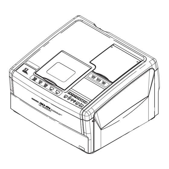
PATTERNLESS EDGER
Brand:
Nidek Medical
| Category:
Edger
| Size: 2 MB
Table of Contents
Table of Contents
4
1 Introduction
9
Outline of the Product
9
Symbol Information
10
2 Safety
11
Cautions During Use
11
Storage
13
Transport
13
Installation
14
Wiring
15
After Use
15
Maintenance and Check
15
Disposal
17
Labels
18
Safety Function
20
3 Configuration
22
Tracing Unit
26
Control Panel for Tracing Unit
26
Display Panel
30
Layout Display
30
4 Operating Procedures
35
Operation Flow
35
Preparation
37
Tracings
38
Tracing Frames
38
Tracing both Rims
38
Semiauto Tracing
39
Tracing Single Rims
39
Tracing Goggle Type Frames
40
Tracing Patterns
41
Tracing Dummy Lenses
42
Tracing During Processing
44
Stopping Tracing
44
Stopping Frame Tracing
44
Stopping Pattern or Dummy Lens Tracing
44
Layouts
45
Selecting Processing Conditions and Inputting Layout Data
45
Inputting Height from Lens Outline
48
Layout of Bifocal Lens
49
Layout of Progressive Power Lens
50
Eye Point Layout
51
Blocking Lenses
52
Blocking in Active Mode
52
Blocking Progressive Power Lenses
52
Blocking in Passive Mode
53
Blocking Bifocal Lenses
54
Processings
55
Beveling
55
Auto Processing Mode
56
Guided Processing Mode
59
Guided Processing Mode (Tilting Function)
63
EX Lens Processing Mode
66
Flat (Rimless) Edging
70
Flat (Rimless) Edging Mode
70
EX Lens Flat (Rimless) Edging Mode
73
Auto Grooving Mode
75
Guided Grooving Mode
77
EX Lens Grooving Mode
81
Other Processings
84
Processing for Frame Changing
84
Processing Half-Eye Lenses
87
Polishing (Type PL4, PLB, and PLB-2R)
90
Chamfering
91
Glass Soft Processing
92
Inputting the Frame Tilt Angle in Flat Edging
93
Checking the Lens Size
94
Retouching Lenses
94
Processing the Opposite Lens
96
Removing the Lens Cup
96
Treatment after Daily Use
97
Daily Checks
98
Daily Check before Use
98
Daily Check after Use
99
Periodical Check
100
5 Other Functions
101
Process Counter
101
Parameter Settings
102
Storing Initial Display
107
Storing and Calling up the Traced Data
108
When the Edger Is Not Connected to the Barcode Scanner
109
When the Edger Is Connected to the Barcode Scanner
110
6 Troubleshooting Guide
112
7 Storage
113
8 Maintenance
114
Wheel Dressing
114
Replacing the Water and Filter (115 V Regions)
118
Replacing the Water (When the Optional FP-100 Is Equipped)
118
Replacing the Water (When the Optional FP-100 Is Not Equipped)
121
Replacing the Water and Filter (230 V Regions)
123
Replacing Fuses
125
Cleaning the Exterior
125
Size Adjustment
126
Adjusting Bevel Position
127
Adjusting Axis Shift
129
Adjusting Axis Shift When Polishing Is Not Done
129
Adjusting Lens Margin Allowed for Finishing
131
PD Adjustment
132
Adjustment for Polishing
133
If a Part of Edge Is Left Unpolished (Type PL4, PLB, and PLB-2R)
133
If the Front Edge or Rear Edge Is Left Unpolished (Type PLB and PLB-2R)
136
Axis Shift Adjustment for Polishing (Type PL4, PLB, and PLB-2R)
137
Adjustment for Grooving
139
Setting of Initial Value for Depth and Width
139
Adjusting Groove Position
140
Adjusting Groove Depth
141
Groove Depth Is Not Made as Designated
141
Groove Depth Is Not Even
142
Adjustment for Chamfering
144
Setting of SFB Mode and Chamfering Amount
144
Adjusting Chamfering Amount
145
Safety Bevel Is Not Made as Designated
145
Chamfering Amount Is Not Even
147
Tracer Calibration
148
List of Consumable Articles
149
9 Specifications
150
10 Accessories
154
NIDEK-Type Accessories
154
WECO-Type Accessories
154
SANTI-Type Accessories
155
Appendix A. Supplement
156
Selection of Tracing
156
Selection of Layout
158
Selection of Blocking
159
Selection of Processing
160
Appendix Berror Code
162
Appendix Cglossary
164
Active Mode
164
Memory Function
165
Passive Mode
165
Advertisement
Nidek Medical LE-9000SX Service Manual (97 pages)
PATTERNLESS EDGER
Brand:
Nidek Medical
| Category:
Edger
| Size: 20 MB
Table of Contents
Table of Contents
3
Introduction
7
Safety
9
General Precautions
9
Maintenance Precautions
9
Troubleshooting
11
Sub-Troubleshooting
13
The Initialization Does Not Start
13
The Display Panel Does Not Display Properly
13
Error Messages Appear
14
Error Code 0001 (Grinding Data Transmission Error) Appears
14
Error Code 0002 (Grinding Data Reception Error) Appears
14
Error Code 0107 (Roughing Does Not Stop.) Appears
15
Error Code 0108 (Grinding Wheel Does Not Turn.) Appears
16
Error Code 0201 (Feelers Cannot be Initialized.) Appears
17
Error Code 0202 (Feelers or Encoder Error) Appears
18
Error Code 0204 (after Measurement of the Rear Surface of the Lens, the Front Surface of the Lens Cannot be Measured.) Appears
19
Error Code 0205 (Abnormal Data for Measured Result of the Lens) Appears
19
Error Code 0206 (the Initial Data Obtained in Lens Shape Measurement Is Abnormal.) Appears
20
Error Code 0207 (There Is a Disparity between the Data at the Starting Point and at the End Point in Lens Shape Measurement.) Appears
20
Error Code 0208
20
Error Code 0209
21
Error Code 0301 (Abnormal y Axis Data for Grinding) Appears
21
Error Code 0302 (Abnormal X Axis Data for Grinding) Appears
21
Error Code 0402 (X Axis Cannot be Initialized.) Appears
21
Error Code 0403 (y Axis Cannot be Initialized) Appears
22
Error Code 0404 (Initialization Error of Θ Axis) Appears
23
Error Code 0405 (Initialization Error of X and y Axes) Appears
23
Error Code 0408 (Initialization Error of F Axis Motor) Appears
24
Error Code 0501 (the Chucking Motor Does Not Run.) Appears
25
Error Code 0602 (the Chamfering/Grooving Unit Does Not Initialize.) Appears
26
Error Code 0603 (Grinding End Sensor Error of the Chamfering/Grooving Unit) Appears
26
Error Code 0604 (Abnormally Attached Position of the Grinding End Sensor of the Chamfering/Grooving Unit) Appears
27
Error Code 0801 (CPU False Interrupt Error) Appears
27
Error Code 0802 (CPU DME Bus Error) Appears
27
Error Code 0900 (EEPROM Writing Error) Appears
27
Error Code 0901 (the Rough Size Parameter Settings Are out of the Specified Range.) Appears
27
Error Code 0902 (the Size Preset Parameter Settings Are out of the Specified Range.) Appears
27
Error Code 0903 (the Bevel Constant Parameter Setting Is out of the Specified Range.) Appears
27
Error Code 0904 (the Settings of the Parameters Related to Wheel Position Are out of the Specified Range.) Appears
27
Error Code 0905 (Frame Memory Verification Error) Appears
28
Error Code 0906 (Frame Memory CRC Check Error) Appears
28
The Instrument Does Not Operate by the Keys on the Control Panel
28
Tracing Cannot be Done Properly
29
Tracing Does Not Start./Tracing Is Not Completed
29
The Stylus Comes off During Tracing
29
Pattern Cannot be Traced
29
The Feelers Do Not Contact the Lens
30
Grinding of a Lens Cannot be Done Properly
30
Water Leaks
30
Water Is Not Supplied
30
Axis Shift Occurs
31
Grinding Takes a Long Time
31
Bevel Position Is Improper
31
Chamfering and Grooving Positions Are Improper
32
Lens Has an Unpolished Area after Polishing
32
Maintenance Message Appears
33
Removing Covers
35
Removing the Cover ASSY
35
Removing the Right, Left and Rear Covers
36
Replacement
37
Replacing the Rocker Switch
37
Replacing the Switching Power Supply
37
Replacing the MAIN Board
38
Replacing the LCD Display
38
Replacing Cable CA24
39
Replacing Cable CA25
39
Replacing the y Axis ASSY
39
Replacing the Tracer ASSY
40
Replacing the 5-Phase Pulse Motor Driver
40
Replacing the Inverter
42
Replacing the Feeler ASSY
42
Replacing the Lens Measuring ASSY
43
Replacing Cable CA26
43
Replacing Cable CA48
44
Replacing Cable CA46
44
Replacing the Pulse Motor for the Rotate Axis
44
Replacing the CD Motor
45
Replacing Cable CA44
45
Replacing the Chamfering/Grooving Unit
46
Replacing the Pulse Motor (E035)
46
Replacing Cable CA38
47
Replacing the BA03 Board
47
Replacing the BA04 Board
47
Replacing the Stylus
48
Replacing the Wheel ASSY
48
Replacing the Carriage ASSY
49
Replacing the Pulse Motor for X Axis
50
Adjustment
51
Installation of the Software
51
Making a Backup of the Parameters
51
Writing the Parameters
51
Writing the Program of the Master CPU
52
Initialization of the EEPROM
52
Writing the Program of the Tracer CPU
53
Adjustment of Chamfering/Grooving Unit
54
Arm Position Adjustment of the Chamfering/Grooving Unit
54
Grinding End Sensor Adjustment of the Chamfering/Grooving Unit
55
Calibration
56
Calibration of the Lens Measuring ASSY
56
Calibration of the Chamfering/Grooving Unit
56
Calibration of the Tracer ASSY
57
Frame Auto Calibration
57
Pattern Auto Calibration
57
Torque Calibration of the Tracer ASSY
57
Full-Calibration of the Tracer ASSY
58
Size and Bevel Adjustment
60
Size Adjustment
60
Bevel Position Adjustment
61
Axis Angle Adjustment
61
Polishing Adjustment
62
Polycarbonate Polish Finishing Allowance Adjustment
62
Polish Level, Polish Axis and Bevel Position Adjustments
63
Polish Size Adjustment
64
Chamfer and Groove Adjustment
64
Height Adjustment of the Chamfering Wheel
64
Groove Position Adjustment
65
Chamfering Wheel Position Adjustment in Beveling
65
Chamfering Wheel Position Adjustment in Flat Edging
65
Chamfer and Groove Axis Adjustment
66
Polishing Wheel Dressing
67
Dressing
67
Applying Compound
68
Chucking Pressure Adjustment
68
Feeler Adjustment
69
Feeler Reference Position Adjustment
69
Feeler Initialization Position Adjustment
69
Initialization Position Adjustment of y and Θ Axes
70
Adjustment of the Lens Measuring ASSY
71
Voltage Adjustment of the Lens Measuring ASSY
71
Axis Check and Adjustment of the Lens Measuring ASSY
72
Tracer ASSY Adjustment
73
Tilt Adjustment of the Stylus
73
Position Adjustment of Cable CA63
73
Cleaning the Pattern Tracing Pin
74
Carriage Adjustment
74
Parameter Check of BL Inverter
75
References
77
Wiring Diagram
77
Connectors and Cables
78
Configuration
80
Labels
82
Error Code Table
84
General Tools
88
Consumables
88
Calibration Jig List
89
Special Key Operation
89
Resetting the Ground Lens Number
89
Recalling the Φ45 Built-In Data
90
Recalling the
90
Built-In Data
90
Displaying the System Setting Mode Screen
90
Grease Application
91
Parameters
93
Parameter List of Brushless Motor
96
Trip List of Brushless Motor Inverter
97
Advertisement
Related Products
Nidek Medical LE-9000EX Express
Nidek Medical LE-9000DX Express
Nidek Medical LE-9000LX
Nidek Medical Express LE-9000 Series
Nidek Medical LE-700
Nidek Medical Lex 1000
Nidek Medical Le 1000
Nidek Medical LEX-DRILL
Nidek Medical LED-1
Nidek Medical LM-600P
Nidek Medical Categories
Medical Equipment
Measuring Instruments
Edger
Oxygen Equipment
Laboratory Equipment
More Nidek Medical Manuals
Login
Sign In
OR
Sign in with Facebook
Sign in with Google
Upload manual
Upload from disk
Upload from URL