Sign In
Upload
Manuals
Brands
Nidec Manuals
Controller
MCE Motion 4000
Nidec MCE Motion 4000 Manuals
Manuals and User Guides for Nidec MCE Motion 4000. We have
1
Nidec MCE Motion 4000 manual available for free PDF download: Manual
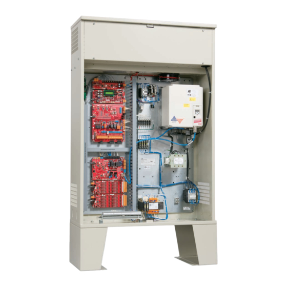
Nidec MCE Motion 4000 Manual (416 pages)
Traction Elevator Controller
Brand:
Nidec
| Category:
Controller
| Size: 19 MB
Table of Contents
Safety and Other Symbol Meanings
3
Safety Precautions
4
Environmental Considerations
4
Air Conditioned Equipment Cabinets
5
In this Manual
6
Table of Contents
7
In this Section
17
Motion 4000 Traction Elevator Control Overview
18
System Features
19
System Component Descriptions
21
Controller Circuit Boards
21
Hand-Held User Interface
22
Car
22
Landing and Positioning
22
Load Weigher
23
Cartop Box
23
Hoistway
24
Motion 4000 Specific Traveler Cable
24
Operating Mode Descriptions
25
Normal Operation
25
Inspection Operation
25
Cartop Inspection
25
In Car Inspection
26
Hoistway Access Inspection
26
Machine Room Inspection
26
Attendant Operation
27
Mode Entry
27
Independent Service
27
Sabbath Operation
27
Emergency Medical Operation
28
Hospital Service
28
Seismic Operation
29
Mode Exit
29
Modifiers
29
Fire Service Operation
29
Emergency Power Operation
29
Generator Backup
29
TAPS Backup
30
Car Recall
30
Capture for Test
30
Test Mode
30
Monitoring and Control Options
31
Imonitor
31
Ireport
31
BMS-Link
32
Mview
32
Section 2. Installation
33
In this Section
33
Job Prints
34
Safety
34
Personal Safety
34
Equipment Safety
35
Preparation
35
Electrical Noise
36
Emi/Rfi
36
Recommended Tools and Test Equipment
36
MCE Wiring Prints
37
Drawing Number Format
37
Nomenclature
37
Power Nomenclature
37
Controller Installation
38
Controller Wiring Guidelines
39
Proper Ground
39
Check for Shorts to Ground
40
AC Power Connections
41
Power Check
41
Motor, Brake, and Encoder Connection
42
Motor Connection
42
Insulation Breakdown Test
42
Motor Wiring
42
MRL or Extended Motor Cables
42
Brake Connection
43
Module Calibration (CAN Only)
43
Module Trim Pots and Function (Discrete Control Only)
43
Module Setup for Adjustment
43
Standard Brake
44
Brake Mechanics
44
Velocity Encoder Installation and Wiring
45
Encoder Wiring
45
Emergency Brake Installation
46
Resetting the Rope Gripper
46
Initial Power up
46
Often Used Procedures
47
How to Check Car Speed
47
How to Place the Car on Automatic Mode Fault Bypass
47
Auto Tuning
48
CT E300 AC Drive
49
Introduction
49
Keypad Overview
49
Keypad Operation
51
Saving Parameters
51
Initializing Mode / Parameters
51
Displaying Non-Default Parameters
51
Accessing Diagnostics
52
AC Drive Setup
52
Set up for Construction Operation
53
Minimal Requirements
53
Jumper Requirements
53
Bypassing Faults on Inspection
54
Resolving Faults
54
Speed and Acceleration Control
55
Required Drive Parameter Settings
55
CT E300 Drive Parameters
56
Required Controller Parameter Settings
63
Acceleration and Deceleration Rates
63
Curves Used for Operating Speeds
63
The F7 Menu
64
Controller Motion Parameters
64
Using Inspection Stations to Run
65
Auto Tune Motor Data, Control Techniques E300
65
Verify Communication, Control Techniques E300
65
Verify Motor Rotation, Control Techniques E300
66
Verify Motor Speed, Control Techniques E300
66
Verify One-Floor-Run Operation, Control Techniques E300
67
Verify Contract Speed Operation, Control Techniques E300
67
Temporary Run Box Hookup
67
Prepare for Inspection Operation
69
Hoistway Safety String
69
Cartop Safety String
69
Hoistway Switches
70
Virtual/Physical/Unused
70
Seismic Equipment
70
Running on Inspection Mode
72
Controller Power up
72
Bypassing Faults on Inspection
73
Finishing Installation
73
Landing/Positioning System
74
Ls-Edge
74
LS-EDGE Installation
75
Top Hanger Assembly
75
Broken Tape Switch
77
Hanging the Tape
77
Sensor Installation
77
Door Zone Magnets
79
Terminal and ETS Magnets
80
Electrical Connections
82
Parameter Settings
83
Permanently Attach Magnets
83
Indicators
83
Elgo
84
Safety String Connection Information
85
Recommendations
85
Installation
86
Hoistway Learn, Elgo
94
Periodic Maintenance Required
94
Left to Right Rail Side Reversal
95
Door Operator and Door Peripherals
98
Door Safety Equipment
98
Door Switches
98
Car Operating Panels, Position Indicators, and Peripherals
98
Fire Service Peripherals
98
Duplex Connection between Controllers
99
Hall Calls, Position Indicators, and Peripherals
99
CE Position Indicators
99
Adjust Brake to 125% of Full Load
100
Traction Auxiliary Power Supply
100
Installation Review
100
In this Section
101
Basic Service Parameters
102
Learning Floor Levels & Counterweight Position
102
ELGO Encoded Magnetic Tape
103
Learn
103
Slowdown Learn, ETS Placement, Elgo
104
LS-EDGE Steel Tape
105
Parameter Settings
105
Hoistway Learn, LS-EDGE
105
Slowdown Learn, ETS Placement
105
Adjusting Floor Heights
107
Door Zone Verification
107
Car and Counterweight Balance
107
Setting Motion/Position Parameters
108
Often Used Procedures
108
How to Check Car Speed
108
How to Place the Car on Inspection Mode Fault Bypass
108
How to Place the Car on Automatic Mode Fault Bypass
108
How to Reset Excessive Faults
108
How to Access/Set the F7 Parameters
109
How to Register Calls from the Controller
109
Setting up Performance Curves
110
Acceleration and Deceleration Rates
110
Curves Used for Operating Speeds
110
Profile Parameters
111
Typical Speed Profile Settings
112
Verify One-Floor-Run Operation
112
Verify Contract Speed Operation
113
Adjust Control Gains
113
Adjust Load Cell Compensation
114
Adjust Inertia Compensation
114
Adjust for Response
115
Additional Adjustment
116
Relevel Operation
116
Brake Coordination
116
Run Tests
116
Adjustment Problems
116
Placing Calls from the Controller
118
Load Testing AC Drives
119
Trouble Slowing with a Full Load
119
Electrical Noise
120
Load Weigher
121
Analog Voltage or Relay Closure
121
Installing the Sensors
122
Installation with 2 to 1 Roping
123
Installing the Control Unit
124
Analog Weigher Output Wiring
125
Relay Closure Output Wiring
125
Controls Overview
125
Menu Order
125
Calibration
126
Manual Calibration with Weights
126
Controller Parameters
128
Auto-Zero Calibration
129
Analog Weigher Additional Calibration
129
Verifying Empty Car Weight for Analog Weighers
129
Adjust the Analog Weigher
130
Troubleshooting
130
Final Tests
131
Often Used Procedures
131
How to Check Car Speed
131
How to Place the Car on Inspection Mode Fault Bypass
132
How to Place the Car on Automatic Mode Fault Bypass
132
How to Access/Set the F7 Parameters
132
How to Reset Excessive Faults
133
Safety String Test
133
SAFH Safety String Test
133
SAFC Safety String Test
133
Motor Contactor Proofing Test
133
Car Stopped at Floor
133
Car in Motion
134
Brake Contactor Proofing Test
134
Car Stopped at Floor
134
Directional Limits Test
134
Down Direction Limit Test
134
Up Direction Limit Test
134
Final Limit Tests
135
Lower Final Limit Test
135
Upper Final Limit Test
135
Car/Counterweight Buffer Tests
135
(Car) Buffer Test
135
Traction Loss Detection (Slip)
136
Inspection Overspeed Test
136
Safety Tests
137
Contract Overspeed Test
138
Leveling Overspeed Test
138
Normal and Emergency Terminal Switch Tests
139
Outer NTS Delta High Speed Test
139
Outer NTS Delta Low Speed Test
139
Continued NTS/ETS Testing
140
ETS Testing
140
ETSL Testing
140
Electrical Governor Test
140
Ascending Car Overspeed Test
141
Safety Tests
141
Car Safety Test
141
Counterweight Safety Test
142
Emergency Brake Test - Unintended Motion, Rope Brake
143
Discrete Brakes - no Brake Module
143
System with Brake Module
143
Emergency or Standby Power Operation
151
Traction Auxiliary Power Supply Test
151
Backup Generator Power Test
152
Final Adjustment
154
In this Section
155
The HC-MPU and HC-MPU-2 Main Processor Units
157
Setting Parameters to Default Values
159
Diagnostic Mode
160
LCD Format
160
Troubleshooting Example
162
F1: Program Mode
165
General Description of Program Mode
165
Changing Parameters
165
Saving Changes
165
Viewing Options Within a Menu
166
Restoring Original Values before Saving
166
Step-By-Step Example
166
Basic Features Menu
167
Fire Service Menu Options
171
Door Operation Menu Options
173
Timer Menu Options
178
Gongs/Lanterns Menu
180
Spare Inputs Menu
181
Viewing and Assigning Spare Inputs
181
Spare Outputs Menu
190
Viewing and Assigning Spare Outputs
190
Extra Features Menu Options
198
UIO Board/Security Enforcement/Connection Order
199
Additional Car Options
205
F2: External Memory Mode
206
Example
206
F3: System Mode
209
Building Security Menu
209
Controller System Menu
210
Passcode Request Menu
211
Load Weigher Thresholds
212
Adjusting Thresholds
212
Analog Load Weigher Learn Function
213
F4: Messages and Floor Labels
215
F5 Menus
217
Controller Utilities
217
Car Call Registration
217
Date/Time, View / Adjust
218
View Event Log
218
Clear Event Log
219
Default TC-MPI Parameters
219
MPI Diagnostic Menu
219
MPI-A Diagnostics
220
MPI-B Diagnostics
228
MPI-C Diagnostics
238
EDG Diagnostics
248
COP Diagnostics Menu
266
System CAN Bus
267
Monitoring and Reporting Menu
268
Diagnostics, Refresh, Reset
268
Terminal Limit Utilities Menu
269
Terminal Switch Learn
269
Perform Terminal Tests
269
ETS Position Locator
269
FCL Brake Unit Utilities Menu
270
FCL Diagnostic Menu
270
FCL Power Data Menu
270
Default TC-FCL Parameters
270
FCL Adjustment Menu
270
F6: Hoistway Learn Operations
271
ELGO Encoded Magnetic Tape
271
LS-EDGE Steel Tape
271
Adjusting Floor Heights
271
F7: Parameters Adjust
272
Changing Parameters
272
Saving Changes
272
Using ID Numbers for Direct Parameter Access
273
Parameters
278
Speed Related Parameters
281
Normal Terminal Switch Parameter Explanations
282
F7 Settings Record
292
F8: Software Revision
293
Status Displays
293
F1 & F8: Board Software Versions
293
In this Section
295
Section 5. Troubleshooting
312
Status and Error Messages
313
Duplexing
332
Dispatching Algorithm
332
Hardware Connections
332
Power Phasing
332
PC Board Quick References
333
HC-CHP CAN Hub and Power Supply Board
334
SW1 DIP Switch Settings
335
HC-CTL Control Board
336
HC-MPU and HC-MPU-2 Main Processor Boards
345
HC-MPU Battery
349
HC-RDR Rear Door Board
350
HC-UIO-2 Universal Input/Output Board
354
Switches
355
Jumpers
356
Test Points
356
Indicators
356
Terminals
356
HC-UIO-2 Switches 7, 8 and 9 Settings
356
HC-UIO-2 Used for Calls
357
Hospital Emergency Operation I/O
357
Troubleshooting
358
Call Inputs and Outputs
359
Spare Inputs and Outputs
360
ICE-COP-2 Car Panel Interface Board
361
Installation Instructions
361
Normal Operation
362
ICE-COP-2 Board Details
362
MC-CPI Car Panel Interface Board
365
Advertisement
Advertisement
Related Products
Nidec MCE Motion 2000 Touch Screen
Nidec MCE Motion 2000 TS
Nidec RINGCONE 400
Nidec 4P10
Nidec 4P63
Nidec 4P12.1
Nidec 4P73
Nidec LEROY-SOMER LSA 49.1 IC6
Nidec D2-018
Nidec D2-034
Nidec Categories
Measuring Instruments
Industrial Equipment
DC Drives
Controller
Test Equipment
More Nidec Manuals
Login
Sign In
OR
Sign in with Facebook
Sign in with Google
Upload manual
Upload from disk
Upload from URL