Sign In
Upload
Manuals
Brands
Nidec Manuals
Controller
Digitax HD M753 EtherCAT
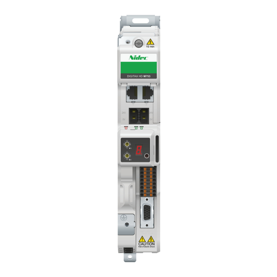
Nidec Digitax HD M753 EtherCAT Manuals
Manuals and User Guides for Nidec Digitax HD M753 EtherCAT. We have
2
Nidec Digitax HD M753 EtherCAT manuals available for free PDF download: User Manual, Installation And Technical Manual
Nidec Digitax HD M753 EtherCAT User Manual (262 pages)
Variable Speed AC drive for Servo and Induction motors
Brand:
Nidec
| Category:
Controller
| Size: 17 MB
Table of Contents
Table of Contents
4
Issue
7
1 Safety Information
9
Warnings, Cautions and Notes
9
Important Safety Information. Hazards
9
Competence of Designers and Installers
9
Responsibility
9
Compliance with Regulations
9
Electrical Hazards
9
Stored Electrical Charge
9
Mechanical Hazards
9
Access to Equipment
9
Motor
10
Mechanical Brake Control
10
Adjusting Parameters
10
Electromagnetic Compatibility (EMC)
10
2 Product Information
11
Introduction
11
Model Number
11
Operating Modes
12
Compatible Position Feedback Devices
13
Nameplate Description
13
Options
14
3 Mechanical Installation
16
SI-Option Module Installation
16
KI-Compact Display Installation
18
KI-Remote Keypad Adaptor Installation
19
4 Electrical Installation
20
External 24 VDC Supply
20
Low Voltage Operation
21
Control Connections
22
Position Feedback Connections
24
Safe Torque off (STO)
30
5 Getting Started
32
Display and Keypad Operation
32
KI-Remote Keypad Operation
34
Menu Structure
36
Menu 0
37
Advanced Menus
37
KI-Remote Keypad Changing the Operating Mode
39
KI-Remote Keypad Saving Parameters
39
Restoring Parameter Defaults
39
Parameter Access Level and Security
39
Displaying Parameters with Non-Default Values Only
40
Displaying Destination Parameters Only
40
6 Basic Parameters
41
Parameter Ranges and Variable Minimum / Maximums
41
Menu 0: Basic Parameters
41
Parameter Descriptions
46
Full Descriptions
48
7 Running the Motor
58
Quick Start Connections
58
Changing the Operating Mode
58
Quick Start Commissioning / Start-Up
60
Quick Start Commissioning / Start-Up Using Connect
67
Setting up a Feedback Device
69
Encoder Simulation Output Set-Up
74
8 Optimization
77
Motor Map Parameters
77
Current Limits
92
Motor Thermal Protection
92
Switching Frequency
92
High Speed Operation
93
9 Ethercat Interface
95
Features
95
What Is Ethercat
95
Ethercat Interface Information
95
Ethercat Interface Terminal Descriptions
95
Network Topology
96
Minimum Node-To-Node Cable Length
96
Quick Start Guide
96
Quick Start Flowchart
98
Saving Parameters to the Drive
98
Station Alias Configuration
98
Process Data Objects (Pdos)
99
Service Data Object (SDO) Parameter Access
99
Canopen over Ethercat (Coe)
99
Ethernet over Ethercat(Eoe)
104
Additional Position Loop Scaling
105
Cyclic Data Loss Behaviour
105
Drive Profile (Cia402) Support
105
Common Profile Features
106
Interpolated Position Mode
113
Vl Velocity Mode
114
Homing Mode
116
Cyclic Sync Position Mode
118
Cyclic Synchronous Velocity Mode
119
Cyclic Synchronous Torque Mode
120
Error Handling
120
Advanced Features
122
Ethercat Protocol Support
122
Advanced Cyclic Data Task Configuration
123
Supported Objects
124
Ethercat Interface - Setup
129
Ethercat Interface - Status and Configuration
129
Ethercat Interface - Eoe Status
129
Ethercat Interface - Resources
129
10 SD Card Operation
130
Introduction
130
SD Card Support
130
Transferring Data
131
Data Block Header Information
132
NV Media / SD Card Parameters
132
SD Card Trips
133
11 Onboard PLC
134
Onboard PLC and Machine Control Studio
134
Benefits
134
Features
134
Onboard PLC Parameters
134
Onboard PLC Trips
135
12 Advanced Parameters
136
Parameter Ranges and Variable Minimum/Maximums
139
Menu 1: Frequency / Speed Reference
148
Menu 2: Ramps
152
Menu 3: Frequency Slaving, Speed Feedback and Speed Control
155
Menu 4: Torque and Current Control
166
Menu 5: Motor Control
170
Menu 6: Sequencer and Clock
177
Menu 7: Analog I/O / Temperature Monitoring
181
Menu 8: Digital I/O
184
Menu 9: Programmable Logic, Motorized Pot, Binary Sum and Timers
188
Menu 10: Status and Trips
194
Menu 11: General Drive Set-Up
196
Menu 12: Threshold Detectors, Variable Selectors and Brake Control Function
198
Menu 13: Standard Motion Controller
208
Menu 14: User PID Controller
212
Menus 15, 16 and 17: Option Module Set-Up
216
Menus 17: Ethercat Interface - Setup
217
Menu 18: Application Menu 1
217
Menu 19: Application Menu 2
217
Menu 20: Application Menu 3
217
Menu 21: Second Motor Parameters
218
Menu 22: Additional Menu 0 Set-Up
220
Status Modes (KI-Compact Display, KI-Remote Keypad and Drive LED Status)
222
Trip Indications
223
Identifying a Trip / Trip Source
223
Trips, Sub-Trip Numbers
225
Internal / Hardware Trips
251
Alarm Indications
252
Status Indications
252
Programming Error Indications
252
Displaying the Trip History
253
Behaviour of the Drive When Tripped
253
Ethercat Diagnostics
253
Ethercat Interface Temperature
253
Error Handling
253
Drive Trip Display Codes
254
Ethercat Interface Trips
254
Updating the Ethercat Interface Firmware
255
Switching Frequency
255
Sync Task Orun Trips
255
Ethercat al Status Codes
255
SDO Abort Codes
256
14 UL Listing Information
257
Motor Overload Protection
258
Advertisement
Nidec Digitax HD M753 EtherCAT Installation And Technical Manual (116 pages)
Variable Speed AC drive for Servo and Induction motors
Brand:
Nidec
| Category:
Controller
| Size: 26 MB
Table of Contents
Table of Contents
3
Digitax HD M75X Series Installation and Technical Guide Issue Number
5
Warnings, Cautions and Notes
6
Important Safety Information. Hazards
6
Competence of Designers and Installers
6
Responsibility
6
Compliance with Regulations
6
Electrical Hazards
6
Stored Electrical Charge
6
Mechanical Hazards
6
Access to Equipment
6
Motor
7
Mechanical Brake Control
7
Adjusting Parameters
7
Electromagnetic Compatibility (EMC)
7
Introduction
8
Model Number
8
Drive Nameplate Description
9
Ratings
10
Operating Modes
11
Drive Features
12
Items Supplied with the Drive
13
Installation and System Accessories
14
Planning the Installation
16
SI Option Module Installation
17
KI-Compact Display Installation
20
KI-Remote Keypad Adaptor Installation
21
Drive Dimensions
23
Ingress Protection Label
26
Enclosure Layout
27
Rear Venting
28
Enclosure Sizing
30
Enclosure Design and Drive Ambient Temperature
32
Drive Cooling Fan Operation
32
Braking Resistor
32
External EMC Filter
36
Terminal Size and Torque Settings
41
Hand Tools Required with Digitax HD M75X Series
42
Routine Maintenance
42
Fan Replacement
43
Power and Ground Connections
48
AC Supply Requirements
50
Supplying the Drive with DC
51
External 24 VDC Supply
53
Low Voltage Operation
54
Ratings
54
Output Circuit and Motor Protection
55
Braking
57
Ground Leakage (PE Current)
60
EMC (Electromagnetic Compatibility)
61
Control Terminals
73
Position Feedback Connections
75
Communication Connections
81
Safe Torque off (STO)
82
Multi Axis System Power Profile and Configuration
84
DC Bus Paralleling Connection Method
87
External 24 VDC Supply Requirements for Multi Axis Systems
90
Communications Link
91
Brake Operation for Multi Axis Systems
91
EMC Filters for Multi Axis Systems
91
Multi Axis System Installation
92
Example Design of a Multi Axis System
95
Drive Technical Data
98
Advertisement
Related Products
Nidec Digitax HD M75X Series
Nidec Digitax HD M75 Series
Nidec Digitax HD M750 Ethernet
Nidec Digitax HD M751 Base
Nidec Digitax HD M754
Nidec HVAC Drive H300
Nidec LEROY-SOMER LSA H 49.1
Nidec H300-03400104A
Nidec H300-06500170A
Nidec H300-03200066A
Nidec Categories
Measuring Instruments
DC Drives
Industrial Equipment
Controller
Test Equipment
More Nidec Manuals
Login
Sign In
OR
Sign in with Facebook
Sign in with Google
Upload manual
Upload from disk
Upload from URL