Sign In
Upload
Manuals
Brands
Newport Electronics Manuals
Controller
INFINITY INF7
Newport Electronics INFINITY INF7 Manuals
Manuals and User Guides for Newport Electronics INFINITY INF7. We have
1
Newport Electronics INFINITY INF7 manual available for free PDF download: Operator's Manual
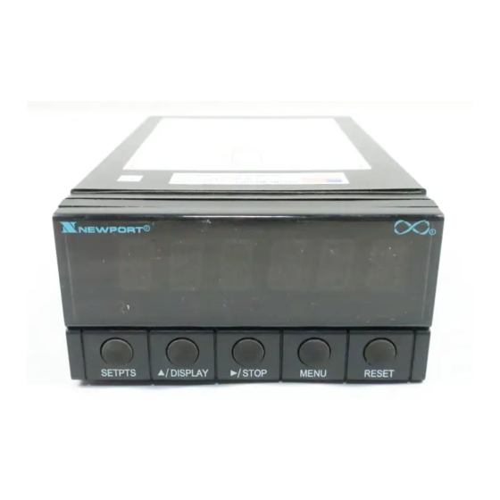
Newport Electronics INFINITY INF7 Operator's Manual (163 pages)
Rate Meter / Totalizer Clock Batch Controller
Brand:
Newport Electronics
| Category:
Controller
| Size: 0 MB
Table of Contents
Table of Contents
3
Safety Considerations
8
Section 1 Introduction
9
Description
9
Features
9
Meter Modes
10
Rate Meter/Totalizer
10
Rate Meter/Totalizer/Square Root Extractor
10
Batch Controller
10
Clock
10
Optional Boards Overview
11
Isolated Pulse Input Board
11
Isolated Analog Input Board
11
Isolated Analog Output Board
12
Isolated Parallel BCD Output Board
12
Dual Relay Output and 4 Relay Output Board
12
Isolated RS-232 Serial Communications Board
12
Isolated RS-485 Serial Communications Board
13
Available Models and Options
13
Section 2 Setup
16
Unpacking
16
Safety Precautions
18
Power Voltage
18
Power Wiring
19
Assembly/Disassembly
19
Opening the Meter
19
Checking and Installing Jumpers
23
Main Board Jumpers
24
Optional Input and Output Board Jumper Information
26
Installing Optional Boards
27
Isolated Pulse Input Board
29
Isolated Analog Input Board
30
Isolated Analog Output Board
31
Isolated Parallel BCD (Binary-Coded Decimal) Output Board
32
Dual Relay and 4 Relay Output Board
33
Isolated RS-232 Serial Communications Board
33
Isolated RS-485 Serial Communications Board
34
Reinserting the Main Board Assembly into the Case
34
Wiring
34
P1 - AC Power Wiring
35
Battery Backup Connections
35
P2 - Control Input/Output Wiring
36
Basic Meter Input Wiring
37
Isolated Pulse Input Board Wiring
37
Isolated Analog Input Board Wiring
37
Isolated Analog Output Board Wiring
37
Isolated Parallel BCD Output Board Wiring
37
Dual Relay and 4 Relay Output Board Wiring
38
Isolated RS-232 or RS-485 Serial Comm. Board Wiring
38
Panel-Mount Assembly
38
Section 3 Front and Rear Features
41
Front-Panel Displays and Buttons
41
Rear Connectors
43
Section 4 Basic Concepts and Approaches to Setup and Configuration
47
Choosing an Operating Mode
47
Mode-Associated Measurements
47
Using Scale Factors
48
Using Offsets
48
Automatic Scale and Offset
48
Overflow Values and Exponential Format
49
Negative-True Logic
49
Different Meter Modes
49
Setpoints
50
Setpoint Assignments
50
Configuring Setpoints
52
Resets and Stops
52
Power-On (Hard) Reset
52
Configuration (Cold) Reset
52
Setpoint-Only Reset
53
Rate and Sq Rt Mode Resets
53
Reset-A
53
Reset-B
54
Reset-C
54
Front-Panel RESET
54
Batch Mode Resets
55
Reset-A
55
Reset-B
55
Reset-C
55
Front-Panel RESET
56
Autoreset
56
Stop
56
Counting up or down
56
Counting up
57
Counting down
58
An Example Showing Setpoint and Reset Control
60
Parameters, Choices, and Settings
62
The Basics of Configuration
63
Lockouts
64
Lockouts and Corresponding Actions
65
Setting Lockouts
68
Removing the S1-A Jumper for Added Security
69
Other Meter Parameters
69
MODE (Operating Mode)
69
CNFG 1 through CNFG 4 (Configuration Parameters)
69
Rate, Sq Rt, Batch
69
AVG.CNF (Running Average Configuration) Rate, Sq Rt
77
IN.SC.OF (Input Scale and Offset) Rate, Sq Rt, Batch
78
OT.SC.OF (Output Scale and Offset) Rate, Sq Rt, Batch
79
RTE DP (Rate Decimal Point) Rate, Sq Rt
81
RTE of (Rate Offset) Rate, Sq Rt
81
RTE SC (Rate Scale) Rate, Sq Rt
82
TOT DP (Total Decimal Point) Rate, Sq Rt, Batch
82
TOT of (Total Offset) Rate, Sq Rt, Batch
83
TOT SC (Total Scale) Rate, Sq Rt, Batch
83
AL TI (Alarm Time) Rate, Sq Rt, Batch
84
GATE T (Gate Time) Rate
84
Baud, Ser.cnf, Dat Ft, Bus Ft, Addres, Ser Ti
85
(Baud Rate, Serial Configuration, Data Format, Bus Format, Device Address, Serial Time) Rate, Sq Rt, Batch
85
SET TI (Set Time) Rate, Sq Rt, Batch
88
BAT DP (Batch Decimal Point) Batch
89
B LOAD (Batch Load) Batch
89
BAT SC (Batch Scale) Batch
90
CAL VZ, CAL VS, Calmaz, and Calmas
90
Step-By-Step Programming Example 1: Rate Mode; Shaft Rpm from Agear-Tooth Detector
90
Determining the Rate Scale (RTE SC)
91
Configuring the Meter
91
Step-By-Step Programming Example 2: Linear Flow; Adding TOTAL to RATE with Excitation from the Basic Meter
93
Determining the Rate Decimal Point (RTE DP) and Rate Scale (RTE SC)
93
Determining the Total Decimal Point (TOT DP) and Total Scale (TOT SC)
94
Configuring the Meter
94
Section 6 Operating the Meter
96
Rate Mode
96
Sq Rt Mode
97
Batch Mode
97
Appendices
99
Basic Meter: General Information, Specifications
99
Jumper Configuration, and Input Connections
99
Isolated Pulse Input Board: General Information
105
Specifications, Jumper Configuration, and Wiring
105
Isolated Analog Input Board: General Information
115
Specifications, Jumper Configuration
115
Wiring, and Calibration
115
Isolated Analog Output Board: General Information, Specifications, Wiring, and Calibration
126
Isolated Parallel BCD Output Board: General Information, Specifications, Jumper Configuration, and Wiring
130
Dual Relay and 4 Relay Output Board: General Information, Specifications, Jumper Configuration, and Wiring
136
G Isolated RS-232 and RS-485 Serial Communications Boards
139
Error Messages
140
Factory Preset Configuration Settings/User Settings
142
Ramp Specifications
155
Specifications
157
Advertisement
Advertisement
Related Products
Newport Electronics INFINITY Series
Newport Electronics INFINITY MICRO-INFINITY ICN77000 Series
Newport Electronics INFINITY MICRO-INFINITY ICN77R500 Series
Newport Electronics INFINITY MICRO-INFINITY ICN77R300 Series
Newport Electronics i Series
Newport Electronics MICRO-INFINITY ICN77300 Series
Newport Electronics MICRO-INFINITY ICN77500 Series
Newport Electronics INFINITY INFCS-B Series
Newport Electronics INFINITY INFCS
Newport Electronics INFINITY INFCS-011B
Newport Electronics Categories
Measuring Instruments
Controller
Thermometer
Monitor
Amplifier
More Newport Electronics Manuals
Login
Sign In
OR
Sign in with Facebook
Sign in with Google
Upload manual
Upload from disk
Upload from URL