Sign In
Upload
Manuals
Brands
Nautel Manuals
Transmitter
V5
Nautel V5 Manuals
Manuals and User Guides for Nautel V5. We have
1
Nautel V5 manual available for free PDF download: User's Installation And Operation Manual
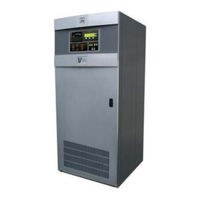
Nautel V5 User's Installation And Operation Manual (141 pages)
FM Broadcast Transmitter
Brand:
Nautel
| Category:
Transmitter
| Size: 1.82 MB
Table of Contents
V10/V7.5/V5/V3.5 Installation and Operation Manual Jul
3
Table of Contents
11
1 General Information
21
Introduction
21
Factory Support
21
Purpose of Manual
21
Purpose of Equipment
21
Mechanical Description
21
Technical Summary
21
Glossary of Terms
22
V10/V7.5/V5/V3.5 FM Broadcast Transmitter
22
RF Output Power Ratings
22
Recommended Site Test Equipment
23
Glossary of Terms
24
2 Preparation for Use and Installation
25
Introduction
25
Preparation for Use
25
Transmitter Room Requirements
25
Transmitter Dimensions
25
Air Flushing
25
Cooling and Heating
25
Transmitter Clearances
25
Transmitter Weight
25
Ac Power Source
26
Ac Power Switch
26
Lightning Protection
26
Station Reference Ground
26
Work Area
26
Cooling Requirements
26
Transmitter Room Considerations
27
Customer Interface Connections
28
Ac Input Connection Options
29
Ac Wiring
30
Antenna Feed Cable
30
Antenna/Rf Output Disconnect
30
Antenna Tower
30
External Control/Monitor Wiring
30
Electrical Power
30
Voltage Stability
30
Power Consumption
32
External Ac Switching
32
Antenna System
32
Digital (IBOC) Operation
32
RF Drive Source(S)
32
RF Feed Cable
32
External Interlocks
33
Remote Control Circuits
33
Single Ended Input Selected
33
On/Off Control
34
Main Exciter Selection
34
Main IPA Selection
34
Remote Control Connections
34
Differential Input Selected
34
Main IPA Power Supply Selection
35
Main Fan Supply Selection
35
Preset Power Level Selection
35
RF Monitor Samples
36
Forward Power Level Sample
37
High Reflected Power Alarm
38
Active IPA Status
39
Available Options
40
Installation
41
Accepting the Shipment
41
Determining Control/Monitor Requirements
41
Installing External Control/Monitor Wiring
41
Unpacking Instructions
41
Visual Inspection
41
Removing Power Module Packing Bracket
42
Installing Ac Power Wiring
43
Ac Power Connection
43
M50 Exciter(S)
45
NE30 Exciter(S)
46
Installing RF Feed Coaxial Cable
47
Commissioning Procedures
48
Precautions
48
Turn-On Prerequisites
48
Initial Turn-On
49
Placing Transmitter On-Air
50
Dimensional Information - V10/V7.5
55
Dimensional Information - V5/V3.5
57
3 Operating Instructions
59
Introduction
59
Emergency Shutdown
59
Precautions
59
Complete Shutdown
59
Turn off RF Output
59
External Safety Interlock
59
Electrostatic Discharge Protection
60
Discharging of Personnel
60
Handling/Storage
60
Tools/Test Equipment
60
Controls and Indicators
60
Stress Current Protection
60
Front Panel
61
Transmitter Front Panel (Primary User Interface)
61
Switching Power Supply Module
62
Control/Display PWB
62
Interconnect PWB
62
Remote Interface PWB
62
Power Module Interface PWB
62
Miscellaneous
62
Transmitter Front Panel - System Diagram Section
62
Front Panel - System Diagram Controls and Indicators
63
Transmitter Front Panel - Control Section
64
Front Panel - Control Section Controls and Indicators
65
Switching Power Supply Module - Front Panel
66
Switching Power Supply Module (PA/IPA) Controls and Indicators
67
Control/Display PWB A43 - Partial View
68
Control/Display PWB - Controls and Indicators
69
Interconnect Pwbs
70
A Interconnect PWB – Controls and Indicators
71
B Interconnect PWB – Transmitter Usage
72
Remote Interface PWB A44
74
Remote Interface PWB - Controls and Indicators
75
Power Module Interface PWB
77
Diagnostic Display
78
Pushbutton Switches
78
Main Screens
78
Transmitter Status Bar
78
Flow Diagram - Diagnostic Display Menu Functions
79
View Faults
80
Change Power, Frequency or Mode
80
View RF Module Status and Fan Speed
81
View Events Log
82
View Software Version
82
Select Metered Parameters
83
Set Real Time Clock
83
Front Panel Metering/Setting Display Contrast
84
Calibrate/Configure External Analog Samples
84
Change Hardware Settings
85
External Analog Sample Outputs
85
Calibrate HD PA and IPA Voltages
86
Calibrate Front Panel Meter
86
Calibrate Meters
86
Enable/Disable Setup Mode
87
Set PA Bias Levels
87
Set Protection Threshold Levels
87
System Configuration
88
Save/Recall Factory Settings
89
Set Main/Standby Operation
90
4 Testing and Adjustment
91
Introduction
91
Operating Precautions
91
Functional Tests
91
General
91
Test Equipment Required
92
Test Prerequisites
92
Optionally Duplicated Modules
93
Transmitter Turn-On
94
Remote Control Checks
94
Remote Control Prerequisites
94
Remote On/Off Control
94
Remote Selection of Active Exciter
95
Remote Selection of Active IPA Module or PA
96
Remote Selection of Active IPA Power Supply
96
Remote Selection of Fan Power Supply
97
Remote Power Trim Control
98
Remote Reset Control
99
Protection Circuit Checks
99
External Interlock
99
Exciter Auto Changeover Check
100
IPA Auto Changeover Check
101
IPA PS Auto Changeover Check
102
Improving Reject Load Power
103
Changing Frequency
104
Changing Ac Input Configuration
104
5 System Level Troubleshooting
105
General
105
Scheduled Maintenance
105
Cleaning the Transmitter
105
Checking Hardware
105
Corrective Maintenance
106
Battery Replacement
106
On-Air Troubleshooting
106
Remote Troubleshooting
106
Scheduled Maintenance Checklist (Example)
106
Local Troubleshooting
107
Electrostatic Protection
107
Off-Air Troubleshooting
107
Discharging of Personnel
107
Handling/Storage
108
Tools/Test Equipment
108
Troubleshooting Front Panel Alarms
108
Stress Current Protection
108
Troubleshooting Guide
110
Exciter Alarm
112
IPA Input Low
112
Low RF Drive
113
Exciter Output Load Fluctuation
113
IPA Input High
113
Exciter Communication Failure
113
Check Exciter
114
Exciter Fault
114
Mode/Frequency Mismatch
114
IPA/PA Alarm
114
IPA Forward High
115
IPA Forward Low
116
IPA Match
116
IPA Reflected High
117
Module Offline
118
High Module Temperature
118
PA Failure
119
Fan Failure
119
Output Network Alarm
120
High Reflected Power
120
SWR Foldback
120
SWR Shutdown
121
Low Forward Power
122
High Reject Load Power and Reject Power Foldback
122
Reject Load Power Shutback
122
Reject Load Power Shutdown
123
High Reject Load Temperature
123
Combiner Top/Bottom Fan Fail
123
Low Voltage Power Supply Alarm
124
LVPS Fault
124
Fan PS Fail and Replacement
125
Ac Mains Alarm
125
Low Ac Alarm
126
Power Supply Alarm
126
RF Power Module Power Supply Fail
126
Backup Battery Low Alarm
127
Changeover Alarm
127
External Alarms
128
Interlock Open Alarm
128
Remote PWB Offline Alarm
128
Fan Removal/Replacement
128
EEPROM Alarms
128
RF Power Module Fan
128
Operation with Defective or Missing
129
Combiner Fans
129
Power Modules(S)
130
RF Output Power Vs Module Failure/Removal
130
Replacing an Rf Power Module
132
RF Power Module Removal
132
RF Power Module Installation
133
Ipa Module Fault Isolation
133
Replacing an Ipa Module
134
IPA Module Removal
134
RF Power Module Modifications for IPA Operation5-30
134
IPA Module Installation
135
Reject Load Module Removal
136
Reject Load Module Installation
136
RF Drive Splitter/Changeover Removal
137
RF Drive Splitter/Changeover Installation
137
IPA Splitter Removal
138
Printed Wiring Board (Pwb) Replacement
139
IPA Splitter Installation
139
Control/Display PWB Replacement
140
Remote Interface PWB Replacement
140
Interconnect PWB Replacement
140
Coaxial Cable Replacement
140
Miscellaneous PWB Replacement
140
Low Power Operation for Antenna Maintenance
141
Advertisement
Advertisement
Related Products
Nautel VS1
Nautel VS2.5
Nautel V7.5
Nautel V3.5
Nautel Vector-LP VR125
Nautel VX150
Nautel VX2
Nautel VX1
Nautel VX3
Nautel VX3.5
Nautel Categories
Transmitter
Recording Equipment
Antenna
Industrial Equipment
Battery Charger
More Nautel Manuals
Login
Sign In
OR
Sign in with Facebook
Sign in with Google
Upload manual
Upload from disk
Upload from URL