Sign In
Upload
Manuals
Brands
National Instruments Manuals
Network Hardware
DAQ PCI-4452
National Instruments DAQ PCI-4452 Manuals
Manuals and User Guides for National Instruments DAQ PCI-4452. We have
2
National Instruments DAQ PCI-4452 manuals available for free PDF download: User Manual
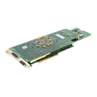
National Instruments DAQ PCI-4452 User Manual (122 pages)
Dynamic Signal Acquisition Device for PCI
Brand:
National Instruments
| Category:
PCI Card
| Size: 0 MB
Table of Contents
Table of Contents
4
About this Manual
9
How to Use the Manual Set
9
Conventions
9
Related Documentation
10
Chapter 1 Introduction
11
About the PCI-445X
11
What You Need to Get Started
12
Unpacking
13
Software Programming Choices
13
National Instruments Application Software
13
NI-DAQ Driver Software
14
Optional Equipment
15
Figure 1-1. the Relationship between the Programming Environment
15
Custom Cabling
16
Analog Cables
16
Analog Accessories
17
Digital Cables (PCI-4451/4452 Only)
17
Chapter 2 Installation and Configuration
18
Software Installation
18
Hardware Installation
18
Device Configuration
19
Chapter 3 Hardware Overview
20
Figure 3-1. Digital Function Block Diagram
20
Figure 3-2. PCI-4451/4452 Analog Function Block Diagram
21
Figure 3-3. PCI-4453/4454 Analog Function Block Diagram
22
Analog Input
23
Input Mode
23
Input Coupling
23
Input Polarity and Input Range
23
Considerations for Selecting Input Ranges
24
Table 3-1. Actual Input Range and Measurement Resolution
24
Analog Output (PCI-4451/4453 Only)
25
Output Mode
25
Output Polarity and Output Range
26
Table 3-2. Actual Output Range and Resolution of the PCI-4451
26
Trigger
27
Figure 3-4. Below-Low-Level Triggering Mode
28
Figure 3-5. Above-High-Level Triggering Mode
28
Figure 3-6. Inside-Region Triggering Mode
29
Figure 3-7. High-Hysteresis Triggering Mode
29
Figure 3-8. Low-Hysteresis Triggering Mode
29
RTSI Triggers
31
Digital I/O (PCI-4451/4452 Only)
31
Figure 3-9. RTSI Bus Signal Connection
31
Timing Signal Routing
32
Programmable Function Inputs (PCI-4451/4452 Only)
32
Device and RTSI Clocks
33
Selecting Sample/Update Clock Frequency
33
Device Configuration Issues
34
Chapter 4 Signal Connections
35
I/O Connectors
35
Analog I/O Connector Signal Descriptions
36
Figure 4-1. Analog Pin Connections for the PCI-4451/4452
36
Table 4-1. Analog I/O Connector Pin Assignment for the PCI-4451/4452
37
Table 4-2. Analog I/O Signal Summary for the PCI-4451/4452
38
Figure 4-2. Analog Pin Connections for the PCI-4453/4454
39
Table 4-3. Analog I/O Connector Pin Assignment for the PCI-4453/4454
40
Table 4-4. Analog I/O Signal Summary for the PCI-4453/4454
41
Digital I/O Connector Signal Descriptions
42
Figure 4-3. Digital Pin Connections
42
Table 4-5. Digital I/O Connector Pin Assignment
43
Table 4-6. Digital I/O Signal Summary
45
Analog Input Signal Connections
46
Figure 4-4. Analog Input Stage of the PCI-4451/4452
46
Figure 4-5. Analog Input Stage of the PCI-4453/4454
47
Types of Signal Sources
48
Floating Signal Sources
48
Ground-Referenced Signal Sources
48
Analog Output Signal Connections
48
Figure 4-6. Analog Output Channel Block Diagram for the PCI-4451
49
Analog Power Connections
50
Figure 4-7. Analog Output Channel Block Diagram for the PCI-4453
50
Digital I/O Signal Connections (PCI-4451/4452 Only)
51
Figure 4-8. Digital I/O Connections
51
Digital Power Connections (PCI-4451/4452 Only)
52
Timing Connections
52
Programmable Function Input Connections (PCI-4451/4452 Only)
53
Acquisition Timing Connections
53
Figure 4-9. Typical Posttriggered Acquisition
53
Figure 4-10. Typical Pretriggered Acquisition
54
PFI0/TRIG1 (EXT_TRIG) Signal
54
CONVERT* Signal
55
EXTSTROBE* Signal (PCI-4451/4452 Only)
55
PFI1/TRIG2 (PRETRIG) Signal
55
Waveform Generation Timing Connections
56
WFTRIG Signal
56
UPDATE* Signal
56
General-Purpose Timing Signal Connections
56
Figure 4-11. EXTSTROBE* Signal Timing
56
Figure 4-12. GPCTR0_SOURCE Signal Timing
57
GPCTR0_GATE Signal
57
GPCTR0_SOURCE Signal
57
Figure 4-13. GPCTR0_OUT Signal Timing
58
GPCTR0_UP_DOWN Signal (PCI-4451/4452 Only)
58
GPCTR1_SOURCE Signal (PCI-4451/4452 Only)
58
Figure 4-14. GPCTR1_SOURCE Signal Timing
59
GPCTR1_GATE Signal (PCI-4451/4452 Only)
59
Figure 4-15. GPCTR1_OUT Signal Timing
60
GPCTR1_OUT Signal (PCI-4451/4452 Only)
60
GPCTR1_UP_DOWN Signal (PCI-4451/4452 Only)
60
Figure 4-16. GPCTR Timing Summary
61
FREQ_OUT Signal (PCI-4451/4452 Only)
62
Field Wiring Considerations
62
Chapter 5 Calibration
64
Loading Calibration Constants
64
Self-Calibration
65
External Calibration
65
Traceable Recalibration
66
Chapter 6 Theory of Analog Operation
67
Functional Overview
67
Analog Input Circuitry
67
Input Coupling
69
Calibration
69
Antialias Filtering
69
Figure 6-1. Input Frequency Response
71
Figure 6-2. Input Frequency Response Near the Cutoff
72
Figure 6-3. Alias Rejection at the Oversample Rate for the PCI-4451/4452
73
Figure 6-4. Alias Rejection at the Oversample Rate for the PCI-4453/4454
74
The ADC
75
Figure 6-5. Comparison of a Clipped Signal to a Proper Signal
75
Noise
76
Analog Output Circuitry (PCI-4451/4453 Only)
77
Anti-Image Filtering
78
Figure 6-6. Signal Spectra in the DAC
79
The DAC
80
Calibration
80
Mute Feature
81
Appendix A Specifications
82
Figure A-1. PCI-4451/4452 Idle Channel Noise (Typical
86
Figure B-1. DB-25 Pinout for the SHC68-DB25 Cable
94
Appendix B Pin Connections
95
Figure B-2. 68-Pin Digital Connector for any Digital Accessory
95
Advertisement
National Instruments DAQ PCI-4452 User Manual (115 pages)
Dynamic Signal Acquisition Device for PCI
Brand:
National Instruments
| Category:
Network Hardware
| Size: 2 MB
Table of Contents
Important Information
3
Table of Contents
4
About this Manual
8
Organization of this Manual
8
Conventions Used in this Manual
9
National Instruments Documentation
10
Related Documentation
10
Customer Communication
10
Chapter 1 Introduction
11
What You Need to Get Started
12
Unpacking
12
Software Programming Choices
13
National Instruments Application Software
13
Optional Equipment
14
Custom Cabling
14
Chapter 2 Installation and Configuration
16
Software Installation
16
Hardware Installation
16
Device Configuration
17
Chapter 3 Hardware Overview
18
Figure 3-1. Digital Function Block Diagram
18
Figure 3-2. Analog Function Block Diagram
19
Analog Input
20
Input Mode
20
Input Coupling
20
Input Polarity and Input Range
20
Considerations for Selecting Input Ranges
21
Table 3-1. Actual Range and Measurement Precision
21
Analog Output
22
Output Mode
22
Output Polarity and Output Range
22
Table 3-2. Actual Range and Measurement Precision
23
Trigger
23
Figure 3-3. Below-Low-Level Triggering Mode
24
Figure 3-4. Above-High-Level Triggering Mode
25
Figure 3-5. Inside-Region Triggering Mode
25
Figure 3-6. High-Hysteresis Triggering Mode
25
Figure 3-7. Low-Hysteresis Triggering Mode
26
RTSI Triggers
26
Digital I/O
27
Figure 3-8. RTSI Bus Signal Connection
27
Device and RTSI Clocks
28
Timing Signal Routing
28
Programmable Function Inputs
28
Selecting Sample/Update Clock Frequency
29
Device Configuration Issues
30
Chapter 4 Signal Connections
31
I/O Connectors
31
Analog I/O Connector Signal Descriptions
32
Figure 4-1. Analog Pin Connections
32
Table 4-1. Analog I/O Connector Pin Assignment
33
Table 4-2. Analog I/O Signal Summary
34
Digital I/O Connector Signal Descriptions
35
Figure 4-2. Digital Pin Connections
35
Table 4-3. Digital I/O Connector Pin Assignment
36
Table 4-4. Digital I/O Signal Summary
38
Analog Input Signal Connections
39
Figure 4-3. Analog Input Stage
39
Types of Signal Sources
40
Floating Signal Sources
40
Ground-Referenced Signal Sources
40
Analog Output Signal Connections
41
Figure 4-4. Analog Output Channel Block Diagram
41
Analog Power Connections
42
Digital I/O Signal Connections
42
Figure 4-5. Digital I/O Connections
43
Digital Power Connections
44
Timing Connections
44
Programmable Function Input Connections
44
Acquisition Timing Connections
45
Figure 4-6. Typical Posttriggered Acquisition
45
PFI0/TRIG1 (EXT_TRIG) Signal
46
CONVERT* Signal
47
PFI1/TRIG2 (PRETRIG) Signal
47
EXTSTROBE* Signal
48
Waveform Generation Timing Connections
48
WFTRIG Signal
48
UPDATE* Signal
48
Figure 4-8. EXTSTROBE* Signal Timing
48
General-Purpose Timing Signal Connections
49
GPCTR0_SOURCE Signal
49
Figure 4-9. GPCTR0_SOURCE Signal Timing
49
GPCTR0_UP_DOWN Signal
50
GPCTR0_GATE Signal
50
Figure 4-10. GPCTR0_OUT Signal Timing
50
GPCTR1_SOURCE Signal
51
GPCTR1_GATE Signal
51
Figure 4-11. GPCTR1_SOURCE Signal Timing
51
GPCTR1_UP_DOWN Signal
52
Figure 4-12. GPCTR1_OUT Signal Timing
52
Figure 4-13. GPCTR Timing Summary
53
FREQ_OUT Signal
54
Field Wiring Considerations
54
Chapter 5 Calibration
56
Loading Calibration Constants
56
Self-Calibration
57
External Calibration
57
Traceable Recalibration
58
Chapter 6 Theory of Analog Operation
59
Functional Overview
59
Analog Input Circuitry
59
Input Coupling
60
Calibration
60
Antialias Filtering
61
Figure 6-1. Input Frequency Response
63
Figure 6-2. Input Frequency Response Near the Cutoff
64
Figure 6-3. Alias Rejection at the Oversample Rate
65
The ADC
66
Figure 6-4. Comparison of a Clipped Signal to a Proper Signal
66
Noise
67
Analog Output Circuitry
68
Anti-Image Filtering
68
The DAC
68
Figure 6-5. Signal Spectra in the DAC
69
Mute Feature
71
Appendix A
72
Channel Characteristics
72
Specifications
72
Dynamic Characteristics
75
Figure A-1. Idle Channel Noise (Typical)
75
Idle Channel Noise (Typical
77
Dynamic Characteristics
78
Analog Trigger
80
Bus Interface
80
Power Requirement
80
Pin Connections
82
Figure B-1. 68-Pin Digital Connector for any Digital Accessory
83
Customer Communication
84
Electronic Services
84
Telephone and Fax Support
85
Technical Support Form
86
Documentation Comment Form
88
Advertisement
Related Products
National Instruments IMAQ PCI-1411
National Instruments DAQ PCI-4451
National Instruments NI PCI-4472
National Instruments NI PCI-4474
National Instruments PCIe-1427
National Instruments PCIe-7851
National Instruments PC-DIO-96
National Instruments PC-DIO-24
National Instruments IMAQ PXI-1411
National Instruments NI PXI-4472
National Instruments Categories
Control Unit
I/O Systems
Controller
Computer Hardware
Measuring Instruments
More National Instruments Manuals
Login
Sign In
OR
Sign in with Facebook
Sign in with Google
Upload manual
Upload from disk
Upload from URL