Sign In
Upload
Manuals
Brands
National Instruments Manuals
Recording Equipment
AT-DIO-32F
National Instruments AT-DIO-32F Manuals
Manuals and User Guides for National Instruments AT-DIO-32F. We have
1
National Instruments AT-DIO-32F manual available for free PDF download: User Manual
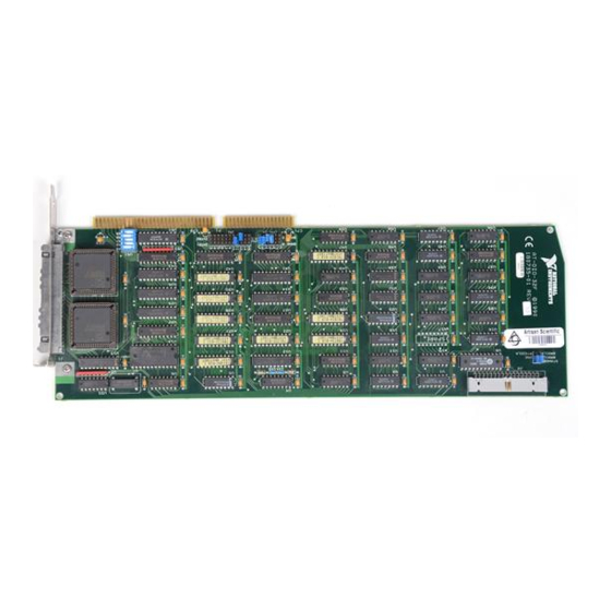
National Instruments AT-DIO-32F User Manual (155 pages)
High-Speed 32-Bit Parallel Digital I/O Interface for the PC
Brand:
National Instruments
| Category:
Recording Equipment
| Size: 3.08 MB
Table of Contents
Table of Contents
5
About this Manual
10
Introduction to the AT-DIO-32F
10
Organization of this Manual
10
Conventions Used in this Manual
11
Related Documentation
11
Customer Communication
11
Chapter 1 Introduction
12
What Your Kit Should Contain
13
Optional Software
14
Optional Equipment
15
Unpacking
16
Chapter 2 Configuration and Installation
17
Board Configuration
17
AT Bus Interface
17
Table 2-1. AT-DIO-32F Factory-Set Jumper and Switch Settings
18
Base I/O Address Selection
20
Figure 2-2. Example Base I/O Address Switch Settings
21
Table 2-2. Default Settings of National Instruments Products for the PC
22
DMA Channel Selection
23
Table 2-3. Switch Settings with Corresponding Base I/O Address and Base I/O Address Space
23
Figure 2-3. DMA Jumper Settings for DMA Channels 5 and 6 (Factory Settings)
24
Figure 2-4. DMA Jumper Settings for DMA Channel 5 Only
24
Table 2-4. DMA Channels for the AT-DIO-32F
24
Interrupt Selection
25
Figure 2-5. DMA Jumper Settings for Disabling DMA Transfers
25
Figure 2-6. Interrupt Jumper Settings IRQ11 and IRQ12 (Factory Settings)
25
RTSI Bus Clock Selection
26
Figure 2-7. Interrupt Jumper Settings for Disabling Interrupts
26
Figure 2-8. Interrupt Jumper Setting IRQ5 Only
26
Figure 2-9. Disconnect from RTSI Bus Clock; Use Onboard Oscillator (Factory Settings)
27
Figure 2-10. Receive RTSI Bus Clock Signal
27
Figure 2-11. Drive RTSI Bus Clock Signal with Onboard Oscillator
27
Table 2-5. Configurations for RTSI Bus Clock Selection
27
Installation
28
Signal Connections
29
I/O Connector Pin Description
29
Figure 2-12. Digital I/O Connector Pin Assignments
29
Signal Connection Descriptions
30
I/O Connector Electrical Specifications
32
I/O Signals Rating
32
Input Signal Specifications
32
Output Signal Specifications
32
Timing Specifications
32
AT-DIO-32F Read and Write Timing
34
Cabling
35
Chapter 3 Theory of Operation
37
Figure 3-1. AT-DIO-32F Block Diagram
37
Address Decoder
38
Bus Transceivers
38
PC I/O Channel Control Circuitry
38
Configuration and Status Registers
38
Data Latches and Drivers
38
Onboard Counters
39
Digital I/O Connector
40
Handshaking Circuitry
40
Figure 3-2. AT-DIO-32F Clock Routing Scheme
40
Figure 3-3. Level Mode - Read
41
Level Mode
41
Figure 3-4. Level Mode - Write
42
Figure 3-5. Leading Edge Mode - Read
43
Leading Edge Mode
43
Figure 3-6. Leading Edge Mode - Write
44
Figure 3-7. Trailing Edge Mode - Read
45
Trailing Edge Mode
45
Interrupt Control Circuitry
46
DMA Control Circuitry
46
Figure 3-8. Trailing Edge Mode - Write
46
RTSI Bus Interface
47
Chapter 4 Programming
48
Register Map
48
Table 4-1. AT-DIO-32F Register Map
49
Register Description
50
Register Description Format
50
Register Sizes
50
Configuration and Status Register Group
51
CFG1 Register
52
CFG2 Register
55
CFG3 Register
58
CFG4 Register
61
STAT Register
63
CNTINTCLR Register
65
DMACLR1 Register
66
DMACLR2 Register
67
Digital I/O Port Register Group
68
Port a Register
69
Port B Register
70
Port C Register
71
Port D Register
72
RTSI Bus Register Group
73
RTSISHFT Register
74
RTSISTRB Register
75
Counter Register Group
76
CNTR1 Register (REQ1 Generator)
77
CNTR2 Register (REQ2 Generator)
78
CNTR3 Register (Timebase Generator)
79
CNTRCMD Register
80
Programming Considerations
84
Initializing the AT-DIO-32F Board
84
Mode 0 Programming
85
Mode 1 Programming
85
Leading Edge Mode
87
Figure 4-1. Level Mode Write Handshake Timing
87
Figure 4-2. Level Mode Read Handshake Timing
87
Figure 4-3. Leading Edge Mode Write Handshake Timing (Lpulsex Cleared)
88
Figure 4-4. Leading Edge Mode Read Handshake Timing (Lpulsex Cleared)
88
Figure 4-5. Leading Edge Mode Read/Write ACK Pulse Width with Lpulsex of CFG4 Set
88
Trailing Edge Mode
89
Figure 4-6. Trailing Edge Mode Write Handshake Timing
89
Figure 4-7. Trailing Edge Mode Read Handshake Timing
89
Data Settling Delay
90
Programmed I/O Transfers
90
Table 4-2. CFG1 Data-Settling Time Settings
90
Input Data Latch
91
Interrupt Handling
91
Table 4-3. Interrupt Condition and Status
92
DMA Transfers
95
32-Bit Transfers
95
Pattern Generation Using Onboard Counters
96
Table 4-4. Counter 3 Programmable Frequency Output
96
Table 4-5. Counters 1 and 2 Programmable Frequency Output (Source = 10 Mhz)
97
Figure 4-8. Pattern Generation
98
Pattern Generation Using an External Signal
100
Programming the RTSI Bus Interface
100
Table 4-6. RTSI Switch Signal Connections
100
Appendix A Specifications
103
Appendix B I/O Connector and Register Descriptions
105
I/O Connector
105
Figure B-1. AT-DIO-32F I/O Connector
105
AT-DIO-32F Register Descriptions
106
CFG1 Register
106
CFG4 Register
106
STAT Register
107
CNTINTCLR Register
107
DMACLR1 Register
107
DMACLR2 Register
107
Port a Register
107
Port B Register
107
Port C Register
108
Port D Register
108
RTSISHFT Register
108
RTSISTRB Register
108
CNTR1 Register (REQ1 Generator
108
CNTR2 Register (REQ2 Generator
108
CNTR3 Register (Timebase Generator
109
CNTRCMD Register
109
Read-Back Command
109
Status Byte
109
Appendix C Application Notes
110
Communicating with a Printer
110
Cabling
110
Sending Files to be Printed
111
AT-DIO-32F to AT-DIO-32F 16-Bit Communications
113
Cabling
114
Sending and Receiving Files with the AT-DIO-32F
114
The AT-DIO-32F and I/O Module Racks
119
Table C-1. Cable Specification for Connections to 8, 16, or 24-Channel I/O Module Racks
119
Appendix D Intel Data Sheet
122
Appendix E
144
Customer Communication
144
Glossary
148
Index
149
Advertisement
Advertisement
Related Products
National Instruments AT-GPIB/TNT (PnP)
National Instruments AT-232
National Instruments AT-485
National Instruments AT-MIO/AI E Series
National Instruments AT-MIO-16
National Instruments AT-MIO E Series
National Instruments AT-MIO-16E-1
National Instruments AT-MIO-16XE-50
National Instruments AT-AI-16XE-10
National Instruments AT-232/4
National Instruments Categories
Control Unit
I/O Systems
Controller
Computer Hardware
Measuring Instruments
More National Instruments Manuals
Login
Sign In
OR
Sign in with Facebook
Sign in with Google
Upload manual
Upload from disk
Upload from URL