MPL PIP20 Manuals
Manuals and User Guides for MPL PIP20. We have 2 MPL PIP20 manuals available for free PDF download: Technical Reference Manual

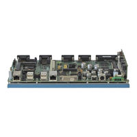
MPL PIP20 Technical Reference Manual (56 pages)
PACKED INDUSTRIAL PC WITH CORE 2 DUO PROCESSOR
Brand: MPL
|
Category: Industrial PC
|
Size: 1 MB
Table of Contents
Advertisement
MPL PIP20 Technical Reference Manual (56 pages)
Brand: MPL
|
Category: Industrial PC
|
Size: 1 MB
Table of Contents
Advertisement