Sign In
Upload
Manuals
Brands
Motorola Manuals
Barcode Reader
MP6000
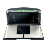
Motorola MP6000 Barcode Scanner Manuals
Manuals and User Guides for Motorola MP6000 Barcode Scanner. We have
1
Motorola MP6000 Barcode Scanner manual available for free PDF download: Integrator Manual
Motorola MP6000 Integrator Manual (200 pages)
Brand:
Motorola
| Category:
Barcode Reader
| Size: 10 MB
Table of Contents
Warranty
4
Revision History
5
Table of Contents
7
About this Guide
13
Introduction
13
Chapter Descriptions
13
Notational Conventions
13
Related Publications
14
Recommended Services Information
14
Chapter 1 Product Overview and Features
17
Introduction
17
Product Overview
18
Configurations
19
Peripherals
24
Supported Auxiliary Hand-Held Scanner
24
EAS Devices
24
Scale Devices
24
USB Flash Drives
24
Customer Side Scanner (CSS)
24
Features of the MP6000
25
Features Summary
29
Chapter 2 Host Interfaces and Cable Pinouts
31
Overview
31
Interfaces, Components, and Communication
32
POS Interfaces and Host Communication
32
Auxiliary Ports and Peripherals
32
Programming Management Tools
33
Application Programming Interfaces
33
Connecting a USB Interface
34
Mp6000 Integrator Guide
34
USB Host Parameters
36
USB Device Type
36
Connecting an RS-232 Interface
42
MP6000 Scanner Only or MP6200/6500 Scale with Single Cable Protocol
42
Price Computational Scale Interface Circuit Drawing
43
Connect MP6000 to RS-232 Host
44
MP6000 with a Dual Cable Scanner/Scale
44
RS-232 Parameters
45
RS-232 Host Parameters
46
RS-232 Host Types
50
RS-232 Host -NCR Variant
60
RS-232 Host -Datalogic Variant
61
RS-232 Device Port Configuration
62
Third Party Scale Parameters
67
Third Party Scale
68
Third Party Scale LED Pin
69
Third Party Scale Zero Pin
71
Connecting an IBM RS-485 Interface
73
IBM RS-485 Host Parameters
74
Hand-Held Scanner Emulation (Port 9B)
76
Non-IBM Scanner Emulation (Port 5B)
77
Connector Pins
83
Aux 1
83
Scale Display Port
83
Aux 2
84
AUX A-B (Stacked USB)
84
Checkpoint Interlock
84
Pos
85
IBM Scale Port Addresses
79
None Selected (Default)
79
Port 6A
80
Port 6B
81
Port 6E
82
Chapter 3 Site Preparation and Installation
87
Overview
87
Site Preparation
88
Ventilation and Spacing Requirements
88
Service Access Requirements
88
Electrical Power Considerations
89
Grounding
89
Checkstand Preparation
90
Liquid Spills and Moisture
90
Tools
90
Vertical Clearance
90
Counter Cutout
91
Ergonomics
91
Installing Components
92
Quick Reference Installation Steps
92
Remove Existing Bioptic Scanner and Accessories
93
Unpacking MP6000 Equipment
93
Pre-Installation Notes
94
Assemble the Dual Head Scale Display
95
Required Tools
95
Install the Scale Display
98
Getting Started
100
Installing
101
Cables and Connections
101
Install the Customer Side Scanner (MX101)
102
Installing the MX101 on the Customer's Right Side (Default) of the Tower Cover
103
Installing the MX101 on the Customer's Left Side of the Tower Cover
107
Affixing the Identification Label
109
Install the MP6000 /Scale
110
Checkstand Counter Cutouts and MP6000 Dimensions
110
Cutout/Dimensions - MP6000 Short
111
Cutout/Dimensions - MP6000 Short (Continued)
112
Cutout/Dimensions - MP6000 Medium
113
Cutout/Dimensions - MP6000 Long
115
Install Sensormatic Coils
119
Install Checkpoint Antenna
121
Trim Kit Installation (if Required)
122
MP6000 Mounting Frame (if Required)
123
Chapter 4 Scale Calibration (Models with a Scale Only)
125
Overview
125
Scale Parameters
125
Scale Calibration Procedure (Scanner/Scale Configurations Only)
126
Scale Configurations
126
Step 1 - Electronic Entry into Calibration Mode
127
Step 2 - Program Legal Parameters
127
Important Notes
127
Legal Scale Units (Unit Selection) - Kilograms or Pounds
127
Legal Scale Dampening Filter
128
Step 3 - Calibration at no LOAD
128
Step 4 - Calibration at LOAD
128
Step 5 - Calibration Success or Failure
131
Calibration Failure
131
Calibration Success
131
Possible Reasons for a Fail
131
Calibration Mode Exit Conditions
131
Verification Test
132
Audit Tallies
135
Scale Configuration Parameters
136
Legal Scale Units
136
Scale Display Configuration
138
Legal Scale Dampening Filter Setting
140
User Interface Displays and Signals
144
Chapter 5 Operating the Scanner
147
Overview
147
Controls and Indicators
148
LED Array Bar
148
Diagnostic LED/7-Segment Display
149
Front Panel Buttons
150
The Three Front Panel User Interface Buttons Are Backlit for Ease of Use
150
Mp6000 Integrator Guide
150
Scale Zero Button (Configurations with Scale Only)
150
Volume/Tone Control Button
150
Sensormatic Manual Activation and Sensormatic Status Button
151
Soft Reset Buttons
151
MP6000 Related Hardware
152
Customer Side Scanner (CSS) - Optional
152
Dual Interval Range Scales
152
Scale (Scanner/Scale Configurations Only)
152
Scale Display (Scanner/Scale Configurations Only)
152
Single Interval Range Scales
152
Installing/Removing the Long Non-Scale and Medium Scale Platters
153
Installing/Removing the Short and Medium Non-Scale Platters
153
Platter
153
Installing/Removing the Long Scale Platter
154
Scan Windows
155
Operating Modes
156
Programming the MP6000
156
Application Programming Interfaces
156
Programming Bar Codes
156
Programming Management Tools
156
USB Staging Flash Drive
157
MP6000 Menu Structure for the USB Staging Flash Drive
157
Manually Staging/Configuring MP6000 Devices
158
Loading Cloning Files
159
123Scan2 Staging Flash Drive Configuration
160
Approved USB Flash Drives for the Flash Drive Well
160
Scanning
161
Weighing Items
162
Electronic Article Surveillance (EAS)
163
EAS Operating Modes and Settings
163
Supported EAS Controllers
163
Checkpoint Controller
164
Sensormatic Controller
164
Sensormatic EAS Hard Tags
164
Sensormatic EAS Soft Tags (Labels)
165
Beeper and LED Conditions
166
Chapter 6 123Scan2
171
Introduction
171
Communication with 123Scan2
171
123Scan2 Requirements
172
Scan Requirements
172
Scanner SDK, Other Software Tools, and Videos
172
Appendix A: MAINTENANCE, TROUBLESHOOTING, and ERROR CODES
173
Overview
173
Maintenance
173
Error Codes
173
Troubleshooting
174
Diagnostic LED 7-Segment Display - Error and Warning Codes
174
LED Display Notes
174
Status Indicator Light
174
Troubleshooting Assistance
175
General Error and Warning Codes
177
Led Display Error and Warning Codes
177
Scale Warning Codes
178
Appendix B: TECHNICAL SPECIFICATIONS
181
Technical Specifications
181
Appendix C Host Interface Character Sets
185
Introduction
185
Tell Us What You Think
197
Advertisement
Advertisement
Related Products
Motorola MK2200-0N0SCKBWT0R - Micro Kiosk MK2200
Motorola MC17A
Motorola MC17
Motorola MT2070
Motorola MC17U
Motorola MC9097-K
Motorola MC32N0 SERIES
Motorola MC9190-NI
Motorola Symbol M2000
Motorola MK1200
Motorola Categories
Cell Phone
Two-Way Radio
Baby Monitor
Cordless Telephone
Radio
More Motorola Manuals
Login
Sign In
OR
Sign in with Facebook
Sign in with Google
Upload manual
Upload from disk
Upload from URL