Sign In
Upload
Manuals
Brands
Motorola Manuals
Radio
Digital Spectra Plus
Motorola Digital Spectra Plus Manuals
Manuals and User Guides for Motorola Digital Spectra Plus. We have
1
Motorola Digital Spectra Plus manual available for free PDF download: Service Manual
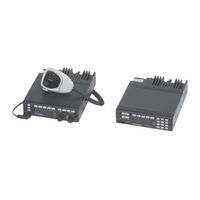
Motorola Digital Spectra Plus Service Manual (248 pages)
UHF/VHF/800 MHz Mobile Radios
Brand:
Motorola
| Category:
Radio
| Size: 2.52 MB
Table of Contents
Table of Contents
3
Foreword
2
Product Safety and RF Exposure Compliance
2
Manual Revisions
2
Computer Software Copyrights
2
Document Copyrights
2
Disclaimer
2
Trademarks
2
Diagram
2
Table of Contents
3
List of Figures
13
VCO Section
14
Commercial Warranty
15
Limited Warranty
15
Motorola Communication Products
15
What this Warranty Covers and for How Long
15
General Provisions
15
State Law Rights
16
How to Get Warranty Service
16
What this Warranty Does Not Cover
16
Patent and Software Provisions
17
Governing Law
17
Model Numbering, Charts, and Specifications
19
Mobile Radio Model Numbering Scheme
19
ASTRO Digital Spectra Motorcycle 15 Watt (Ranges 1 and 2) Model Chart
20
ASTRO Digital Spectra Motorcycle 15 Watt (Ranges 3 and 3.5) Model Chart
21
ASTRO Digital Spectra VHF 10-25 Watt Model Chart
22
ASTRO Digital Spectra VHF 10-25 and 50-110 Watt Model Chart
23
ASTRO Digital Spectra UHF 10-25 Watt Model Chart
25
ASTRO Digital Spectra UHF 20-40 Watt Model Chart
26
ASTRO Digital Spectra UHF 50-110 Watt Model Chart
28
ASTRO Digital Spectra 800 Mhz Model Chart
30
ASTRO Digital Spectra Plus VHF 25-50 and 50-110 Watt Model Chart
31
ASTRO Digital Spectra Plus 800 Mhz Model Chart
33
VHF Radio Specifications
35
UHF Radio Specifications
36
800 Mhz Radio Specifications
37
Chapter 1 Introduction
39
General
39
Diagram
39
Notations Used in this Manual
40
Chapter 2 General Overview
41
Introduction
41
Analog Mode of Operation
42
ASTRO Mode of Operation
42
Control Head Assembly
42
Display (W3 Model)
42
Display (W4, W5, and W7 Models)
42
Display (W9 Model)
43
Vacuum Fluorescent Display Driver
43
Vacuum Fluorescent Voltage Source (W9 Model)
43
Controls and Indicators
43
Status Leds
43
Backlight Leds
43
Vehicle Interface Ports
44
Power Supplies
44
Ignition Sense Circuits
44
Power Amplifier
45
Gain Stages
45
Power Control
45
Circuit Protection
45
DC Interconnect
45
Front-End Receiver Assembly
46
RF Board Basic
46
Voltage-Controlled Oscillator
46
VHF Radios
46
UHF and 800 Mhz Radios
47
Command Board
47
ASTRO Spectra Vocoder/Controller Board
47
Radio Power
48
General
48
B+ Routing for ASTRO Spectra VOCON Board
49
Figure 2-1. DC Voltage Routing Block Diagram
49
Figure 2-2. ASTRO Spectra B+ Routing for Vocoder/Controller (VOCON) Board
50
Chapter 3 Theory of Operation
51
RF Board
51
General
51
Figure 3-1. Prescaler IC Block Diagram
52
Figure 3-2. Synthesizer IC Block Diagram
52
Synthesizer
53
Reference Frequency Generation
53
First VCO Frequency Generation
53
Programmable Reference Divider
54
Figure 3-3. Loop Divider Waveforms
54
Phase Modulator
55
Loop Filter
55
Auxiliary Control Bits
55
Figure 3-4. Loop Filter Schematic
55
Second VCO
56
Power Distribution
56
Receiver Back-End
56
First if
56
Abacus II IC
57
Command Board
58
Microcontroller and Support Ics
58
Serial Input/Output IC
58
Power-Up/-Down Sequence
59
Regulators
60
Reset Circuits
60
Table 3-1. Integrated Circuits Voltages
60
Serial Communications on the External Bus
61
Figure 3-5. Power-On Reset
61
Synchronous Serial Bus (MOSI)
62
Received Audio
62
Microphone Audio
62
Transmit Deviation
63
Line Driver
63
Flash Programming
63
Encryption Voltages
63
Regulator and Power-Control IC
64
Figure 3-6. Transmitter Attack Time
64
ASTRO Spectra VOCON Board
65
General
65
Controller Section
65
Figure 3-7. VOCON Board - Controller Section
66
Vocoder Section
67
RX Signal Path
68
Figure 3-8. VOCON Board - Vocoder Section
68
Figure 3-9. DSP RSSI Port - RX Mode
69
TX Signal Path
71
Figure 3-10. DSP RSSI Port - TX Mode
71
Controller Bootstrap and Asynchronous Buses
72
Figure 3-11. Host SB9600 and RS232 Ports
73
Vocoder Bootstrap
74
Serial Peripheral Interface (SPI) Bus
74
Controller Memory Map
74
Figure 3-12. Controller Memory Mapping
75
Vocoder Memory Map
76
Figure 3-13. Vocoder Memory Mapping
77
MCU System Clock
78
DSP System Clock
78
Radio Power-Up/Power-Down Sequence
78
VOCON BOARD Signals
79
Table 3-2. VOCON Board Address Bus (A) Pinouts
79
Table 3-3. VOCON Board Address Bus (HA) Pinouts
80
Table 3-4. VOCON Board Data Bus (D) Pinouts
80
Table 3-5. VOCON Board Data Bus (HD) Pinouts
81
U204 (Mcu)
82
Table 3-7. U206 (SLIC)
84
Table 3-8. VOCON U405 (DSP)
86
Table 3-9. VOCON U406 (ADSIC)
86
ASTRO Spectra Plus VOCON Board
88
General
88
ASTRO Spectra Plus Controller Section
88
ASTRO Spectra Plus Vocoder Section
89
Figure 3-14. ASTRO Spectra Plus VOCON Board - Controller Section
89
Figure 3-15. ASTRO Spectra Plus VOCON Board - Vocoder Section
90
ASTRO Spectra Plus RX Signal Path
91
Figure 3-16. ASTRO Spectra Plus RX Mode
91
ASTRO Spectra Plus TX Signal Path
92
Figure 3-17. ASTRO Spectra Plus TX Mode
92
ASTRO Spectra Plus Controller Bootstrap and Asynchronous Busses
93
ASTRO Spectra Plus Serial Peripheral Interface Bus
94
ASTRO Spectra Plus MCU and DSP System Clocks
94
Figure 3-18. ASTRO Spectra Plus Host SB9600 and RS232 Ports
94
ASTRO Spectra Plus Voltage Regulators
95
Figure 3-19. ASTRO Spectra Plus VOCON DC Distribution
95
ASTRO Spectra Plus Radio Power-Up/Power-Down Sequence
96
Voltage Control Oscillator
97
VHF Band
97
General
97
DC Voltage Supplies
97
Vco
97
Synthesizer Feedback
98
RX Buffer Circuitry
98
Frequency Divider and TX Buffer Circuitry
98
UHF Band
98
General
98
Super Filter 8.6 V
99
Vco
99
Receive Mode (AUX2* Low)
99
Transmit Mode (AUX2* High)
99
Bandshift Circuit
99
Output Buffer
99
First Buffer
99
Doubler
100
Synthesizer Feedback
100
Second Buffer
100
Receive/Transmit Switch
100
800 Mhz Band
100
General
100
Super Filter 8.6 V
100
Vco
100
Receive Mode-AUX 1* and AUX 2* High
101
Transmit Mode-AUX 1* High; AUX 2* Low
101
Talkaround Mode-AUX 1* Low; AUX 2* Low
101
VCO Buffer
101
First Buffer Circuit
101
Doubler
101
Second Buffer
102
K9.4 V Switch
102
Receiver Front-End
103
VHF Band
103
General
103
Theory of Operation
103
UHF Band
103
Theory of Operation
104
800 Mhz Band
104
General
104
Power Amplifiers
105
VHF Band Power Amplifiers
105
High-Power Amplifier
105
Transmitter
105
Antenna Switch and Harmonic Filter
106
Power Control Circuitry
107
Figure 3-20. RPCIC Block Diagram
107
25/10-Watt Power Amplifier
109
Antenna Switch and Harmonic Filter
110
Power Control Circuitry
110
Figure 3-21. Regulator/Power Control IC Block Diagram
111
50-Watt Power Amplifiers
113
Transmitter
113
Figure 3-22. 50-Watt Power Amplifier Block Diagram
113
Antenna Switch and Harmonic Filter
114
Power Control Circuitry
115
Figure 3-23. Regulator/Power Control IC Block Diagram
115
UHF Band Power Amplifiers
118
High-Power Amplifier
118
Transmitter
118
Figure 3-24. UHF High-Power, Power Amplifier Block Diagram
118
Antenna Switch and Harmonic Filter
119
Power Control Circuitry
119
Figure 3-25. RPCIC Block Diagram
120
40-Watt Power Amplifier
122
Transmitter
122
Antenna Switch and Harmonic Filter
123
Power Control Circuitry
124
Figure 3-26. RPCIC Block Diagram
124
800 Mhz Band Power Amplifiers
127
15- and 35-Watt Amplifiers
127
Transmitter
127
Antenna Switch and Harmonic Filter
128
Power Control Circuitry
129
Figure 3-27. RPCIC Block Diagram
129
Temperature Sensing
131
Chapter 4 Troubleshooting Procedures
133
ASTRO Spectra Procedures
133
Handling Precautions
133
Voltage Measurement and Signal Tracing
134
Power-Up Self-Check Errors
134
Table 4-1. Power-Up Self-Check Error Codes
134
Power-Up Sequence
135
RF Board Troubleshooting
137
Display Flashes "FAIL 001
137
Table 4-2. Voltage by Location
137
Incorrect Values at U602, Pin 19
138
Incorrect Values at U602 Pin 25 (MODULUS CONTROL)
139
Incorrect Voltage at Positive Steering Line
139
Incorrect Values at U602, Pin 27
139
Review of Synthesizer Fundamentals
139
Table 4-3. Feedback Frequency Ranges
139
Second VCO Checks
140
Troubleshooting the Back-End
140
Standard Bias Table
141
Table 4-4. Standard Operating Bias
141
ASTRO Spectra Plus Procedures
142
ASTRO Spectra Plus Power-Up Self-Check Errors
142
Table 4-5. ASTRO Spectra Plus Power-Up Self-Check Error Codes
142
ASTRO Spectra Plus Power-Up Self-Check Diagnostics and Repair
143
ASTRO Spectra Plus Standard Bias Table
144
Table 4-6. ASTRO Spectra Plus Standard Operating Bias
144
VCO Procedures
145
VHF Band
145
Figure 4-1. VCO Block Diagram - VHF Band
146
VCO Hybrid Assembly
147
No or Low Output Power (TX or RX Injection)
147
No or Low Modulation
147
UHF Band
147
Table 4-7. VCO Frequency
147
Out-Of-Lock Condition
148
No or Low Output Power (TX or RX Injection)
148
No or Low Modulation
149
Figure 4-2. VCO Block Diagram - UHF Band
149
800 Mhz Band
150
VCO Hybrid Assembly
150
Out-Of-Lock Condition
150
Figure 4-3. VCO Block Diagram - 800 Mhz Band
150
No or Low Output Power (TX or RX Injection)
151
No or Low Modulation
151
Receiver Front-End (RXFE)
152
VHF Band
152
UHF Band
152
800 Mhz Band
152
Power Amplifier Procedures
153
VHF Band
153
High-Power Amplifier
153
General Troubleshooting and Repair Notes
153
Figure 4-4. Connector Pin-Out - High-Power Amplifier
154
Table 4-8. Power Control DC Voltage Chart
155
PA Functional Testing
157
Table 4-9. LLA and 2Nd Stage Typical Voltages
158
Power Control and Protection Circuitry
160
25/10 Watt Power Amplifier
161
General Troubleshooting and Repair Notes
161
PA Functional Testing
162
Table 4-10. DC Voltages and Input Power Chart
162
Figure 4-5. PA Test Adapter, 25/10 Watt Power Amplifier
163
Table 4-11. Power Control DC Voltage Chart
163
Localizing Problems
166
Table 4-12. Antenna Switch DC Voltage Chart
166
Isolating Failures
167
Table 4-13. LLA and Driver Typical Voltages
167
Power Control and Protection Circuitry
169
Watt Power Amplifiers
170
General Troubleshooting and Repair Notes
170
PA Functional Testing
171
Table 4-14. DC Voltages and Input Power Chart
171
Figure 4-6. PA Test Adapter, 50 Watt Power Amplifier
172
Table 4-15. Power Control DC Voltage Chart
172
Localizing Problems
174
Isolating Failures
175
Table 4-16. LLA and Pre-Driver Typical Voltages
175
Power Control and Protection Circuitry
177
UHF Band
179
High-Power Amplifier
179
General Troubleshooting and Repair Notes
179
Figure 4-7. Connector Pin-Out - High-Power Amplifier
180
Table 4-17. Power Control DC Voltage Chart
181
PA Functional Testing
183
Table 4-18. LLA and 2Nd Stage Typical Voltages
184
Power Control and Protection Circuitry
186
Watt Power Amplifiers
188
General Troubleshooting and Repair Notes
188
Figure 4-8. Block Diagram for Spectra High-Power Power Amplifier
188
PA Functional Testing
189
Figure 4-9. PA Test Adapter, 40 Watt Power Amplifier
190
Table 4-19. DC Voltages and Input Power Chart
190
Table 4-20. Power Control DC Voltage Chart
191
Localizing Problems
193
Table 4-21. Antenna Switch DC Voltage Chart
193
Isolating Failures
194
Table 4-22. LLA and Pre-Driver Typical Voltages
194
Power Control and Protection Circuitry
196
800 Mhz Band
198
Watt and 35 Watt Power Amplifiers
198
General Troubleshooting and Repair Notes
198
PA Functional Testing
199
Figure 4-10. PA Test Adapter, 15 and 35 Watt Power Amplifier
199
Table 4-23. DC Voltages and Input Power Chart
200
Table 4-24. Power Control DC Voltage Chart
200
Localizing Problems
203
Table 4-25. Antenna Switch DC Voltage Chart
203
Isolating Failures
204
Power Control and Protection Circuitry
206
ASTRO Digital Spectra and Digital Spectra Plus Mobile Radios Basic Service Manual
206
Chapter 5 Troubleshooting Charts
209
Introduction
209
List of Troubleshooting Charts
209
RF Board Back-End
209
Command Board
209
Radio Power-Up Fail
209
Bootstrap Fail
209
01/90, General Hardware Failure
209
01/81, Host ROM Checksum Failure
209
01/82 or 002, External EEPROM Checksum Failure
209
01/88, MCU (Host MC) External SRAM Failure
217
01/92, Internal EEPROM Checksum Failure
217
02/A0, ADSIC Checksum Failure
218
02/81, DSP ROM Checksum Failure
218
02/88, DSP External SRAM Failure U414
219
02/84, DSP External SRAM Failure U403
219
02/82, DSP External SRAM Failure U402
220
02/90, General DSP Hardware Failure
220
09/10, Secure Hardware Failure
221
No RX Audio
222
No TX Modulation
223
Key Load Fail
224
800 Mhz Receiver Front-End Hybrid
225
UHF Receiver Front-End Hybrid
225
VHF Receiver Front-End Hybrid
226
ASTRO Spectra Plus VOCON Power-Up Failure
227
ASTRO Spectra Plus VOCON DC Supply Failure
228
ASTRO Spectra Plus VOCON TX Modulation Failure Sheet 1 of 4
229
ASTRO Spectra Plus VOCON TX Modulation Failure Sheet 2 of 4
230
ASTRO Spectra Plus VOCON TX Modulation Failure Sheet 3 of 4
231
ASTRO Spectra Plus VOCON TX Modulation Failure Sheet 4 of 4
232
ASTRO Spectra Plus VOCON RX Audio Failure
232
ASTRO Spectra Plus VOCON Secure Hardware Failure
233
ASTRO Spectra Plus VOCON Key Load Fail
234
Chapter 6 Troubleshooting Waveforms
235
Introduction
235
ASTRO Spectra Waveforms
235
Waveform W1: Power-On Reset Timing
235
Waveform W2: DSP SSI Port RX Mode
236
Waveform W3: DSP SSI Port TX Mode CSQ
236
Waveform W4: ABACUS Programming at Mode Change
237
Waveform W5: ABACUS/ADSIC Interface
237
Waveform W6: SPI Bus Programming ADSIC
238
Waveform W7: Receive Audio
238
Waveform W8: Transmit Audio
239
Waveform W9: Power-Down Reset
239
Waveform W10: ADSIC 2.4 Mhz Reference
240
ASTRO Spectra Digital Plus VOCON Board Waveforms
241
32 Khz Clock Waveform
241
Mhz Clock Waveform
242
TX Modulation out Waveform
242
Differential ADDAG Output Waveform
243
TX SSI Waveform
243
SPI Bus Waveform
244
TX 1 Khz Tone Waveform
244
Serial Audio Port Waveform
245
RX Audio Waveform
245
RX BBP Waveform
246
Secure Interface Waveform
246
Khz Frame Sync for Security Circuitry Waveform
247
Advertisement
Advertisement
Related Products
Motorola Spectra
Motorola Spectra SmartNet E2
Motorola SYNTOR X
Motorola Saber III Securenet
Motorola SM50
Motorola ST7500
Motorola Spectra Privacy Plus
Motorola Spectrum Series
Motorola SP007
Motorola Sprint PCS Vision
Motorola Categories
Cell Phone
Two-Way Radio
Baby Monitor
Cordless Telephone
Radio
More Motorola Manuals
Login
Sign In
OR
Sign in with Facebook
Sign in with Google
Upload manual
Upload from disk
Upload from URL