Sign In
Upload
Manuals
Brands
Moog Manuals
Servo Drives
T200
Moog T200 Manuals
Manuals and User Guides for Moog T200. We have
1
Moog T200 manual available for free PDF download: User Manual
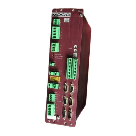
Moog T200 User Manual (374 pages)
Programmable Servo Drive
Brand:
Moog
| Category:
Servo Drives
| Size: 8 MB
Table of Contents
Section 1
6
Table of Contents
6
T200 Overview
10
Section 2
11
Introduction
12
T200 Models
13
Environmental Specifications
15
Design Standards
16
Power Ratings Specifications
17
Units with A.C. Mains Input Interface (T200-310 to T200-710)
18
Units with D.C. Bus Input Interface (T200-300, T200-400, T200-500)
19
Optional Control Logic Backup Power
19
Power Amplifier
20
General Functional Specifications
21
Digital Inputs
21
Digital Outputs
22
Other I/O
22
Software Control Modes
23
Safety Instructions
24
Section 2: Safety Instructions
25
General
26
Safety Regulations
27
Safety
28
Safety
31
Equipment Safety
31
Safety Requirements for Cables
33
A) Requirements - Conductors and Cables
33
B) Wiring Practices - Connections and Routing
33
C) Wiring Practices - Conductor and Cable Runs
33
D) Wiring Practices - Conductors of Different Circuits
34
E) Wiring Practices - Identification of Conductors
34
F) Wiring Practices - Identification of the Protective Conductor
34
G) Wiring Practices - Identification of the Neutral Conductor
34
H) Wiring Practices - Wiring Inside Enclosures
34
I) Wiring Practices - Wiring Outside Enclosures
35
J) Wiring Practices - Ducts, Connection and Junction Boxes
36
EMC Requirements for Cables
37
Electromagnetic Compatibility (Emc)
38
Specific Electromagnetic Compatibility (EMC) Requirements
38
Section 3: Wiring and Installation
41
System Components
46
Mains Power Interface
46
Single-Phase Mains Connection
47
Three Phase Mains Connection
47
Input Circuit Breaker - (User Supplied)
48
Serial Set-Up Terminal (User-Supplied)
50
Control-Backup Power Input (User Supplied)
50
VD.C. Control-Backup Power Supply
50
A.C. Control-Backup Power Supply
51
Note on Cases Where the User Does Not Need to Use a Control-Backup Power-Supply
51
Brushless Servo Motors
51
Brushless Motor Brake 24V Power Supply
51
Heatsinks and Climatic Control
51
Mating Connectors, Cables and Wiring
52
Option Cards
52
Wiring and Installation
46
Equipment Mounting
53
CE Items for Mechanical Installation
60
Power Dissipation
61
Section 4: Motor Guide
133
Motor Servo-Drive System
135
Global Motor Models and Electrical Types
135
Motor Model Identification Scheme
135
Motor Nameplate
136
Motor Part Number Cross Reference
137
Motor Electrical Type Cross Reference
138
Configuring the Motor in the T200 Servo-Drive
139
Motor Configuration Via Windrive
139
Motor Configuration Via Hand Held Terminal
139
Motor-Drive Selection
141
Motor Performance Data
142
Mounting and Installation
144
Motor Dimensions
144
Motor Installation Guideline
146
Rated Bearing Load Capacity
147
Coupling
150
Runout
151
Design Standards
152
Motor Brake Data
155
Section 5: Quick-Start
157
Section 4 Table of Figures
157
Getting Started
158
Initial Preparation
158
Power up Sequence
158
Figure 5.1:- Selecting the Motor
159
Preliminary Step:- Activate Windrive
159
Starting the Drive
159
Step 1:- Selection of the Motor
159
Figure 5.2:- Selecting the Reference Source
160
Step 2:- Setup the Reference Source
160
Figure 5.3:- Selecting the Velocity and Torque Limits
161
Figure 5.4:- Setting up the Limit Switches
161
Step 3:- Setup of the Torque and Velocity Limits
161
Step 4:- Setting Limit Switch Parameters
161
Figure 5.5:- Setting up the Control Mode and Tuning Parameters
162
Step 5:- Basic Tuning
162
Figure 5.6:- Setting up the Encoder Simulation
163
Step 6:- Encoder Simulation
163
Figure 5.7:- Regen Resistor Configuration
164
Figure 5.8:- Setting up the EEPROM
164
Step 7:- Regen Resistor Configuration
164
Step 8:- Saving the Settings
164
Figure 5.9:- Enable/Disable/Quick-Stop Floating Toolbar
165
Power-Down Sequence
165
Step 9:- Enabling the T200 and Causing Movement of the Motor
165
T200 Functional Overview
167
T200 Functional Overview
169
Introduction
170
T200 Functionality Overview
171
Analog Command Interface
171
Controller Area Network (CAN) Interface Mode
172
Stepper Motor Interface Mode
173
Digital Inputs Velocity Interface Mode
174
Standalone Motion-Controller Custom Interface Mode ("Point")
175
T200 Conventions
176
Direction of Rotation
176
Power Interface Section
177
T200 Model Types and High Power Interface
177
High Power Section Description
177
High Power Circuit Description
180
Input and Output Functional Description
182
Reference Analog (±10V Command) Input
182
Spare Analog (Analog Torque Limit) Input
182
TP1 Analog Output
182
TP2 Analog Output
183
Limit Switch Function
183
Power Ready Input
184
Automatic and Manual Power Settings
184
Torque-Velocity Control Mode Switching
185
Rotation Direction
185
Programmable Speed Functions
186
Thermal Limiting Indication
186
Drive Power Status
187
Speed Torque Achieved Indication
188
System Ready Indication
189
Brake Control
189
Function Generator
190
Torque and Velocity Function Generator
190
Position Function Generator
191
Control Loop Overview
193
Torque Mode
193
Torque Command Sources
195
Torque-Command Analog Offset Adjust
195
Rate Limiting in Torque-Mode
196
Programmable Torque Limiting in Torque Mode
197
Programmable Velocity Limiting in Torque Mode
197
Analog Torque Limiting in Torque Mode
198
Torque Mode Functional Block Diagram
199
Velocity Mode
201
Programmable Torque Limiting in Velocity Mode
201
Programmable Velocity Limiting in Velocity Mode
201
Velocity Mode Offset Adjust
201
Velocity Mode Reference Sources
201
Rate Limiting in Velocity-Mode
202
Analog Torque Limiting in Velocity Mode
203
Velocity Mode Functional Block Diagram
203
Velocity Loop Tuning
204
Velocity Observer Tuning and Usage
205
Auto-Tuning the Velocity Loop Gains and the Velocity Observer
208
Monitoring the Velocity Tracking
209
Position Mode
210
Position Mode Offset Adjust
210
Position Mode Reference Sources
210
Programmable Torque Limiting in Position Mode
210
Programmable Velocity Limiting in Position Mode
210
Analog Torque Limiting in Position Mode
211
Position Limits in Position Mode
211
Velocity Rate Limiting in Position Mode
211
Position Mode Functional Block Diagram
212
Position Loop Tuning
213
Monitoring the Velocity Tracking in Position Mode
214
Monitoring the Position Tracking in CAN Interpolation Mode
215
Fault Detection
216
Faults and User Indication in the T200
216
Fatal Faults and Non-Fatal Faults
216
Faults and Warnings
216
Fatal Faults
217
Non Fatal Faults
219
T200 Warnings
221
Fault History Record
222
Fault Indication Via Digital Outputs
223
Mode 1: Fault Indication Via Digital Outputs Disabled
223
Mode 2: Fault Indication Via Digital Outputs Enabled
224
Self Protection
226
Sources of Torque Limits
226
Power Amplifier Thermal Protection Mechanism
226
Motor Protection Thermal Protection Mechanism
226
Cabling and Interconnect Protection Scheme
226
Regeneration Resistor Protection Scheme
227
Encoder Simulation Function
229
Incremental Encoder Input
231
Stepper Motor Interface
233
Hardware Limit Switches
233
Following Error Detection
234
Communications Interfaces
235
Axis Identification
235
Communications Protocol
235
Introduction
235
Serial Link Signal Specification
235
Message / Reply Formats
236
Modifying T200 Parameters
237
Monitoring T200 Parameters
239
Block Data Format
241
Parameter Set Description
243
Parameter Storage
244
Personality Plug
245
Format of Log Files
246
Section 7: Windrive
251
Windrive
252
Windrive Software Set-Up
255
System Requirements
255
Installation
255
Introduction
255
Starting Windrive
256
Communication Link between Windrive and Drive
256
Rs232 and Rs485 Communication
258
RS232 Connection
259
RS485 Communication
260
RS485 Interfacing Connection
260
RS232/RS485 Adapter
261
Password Protection
262
Off-Line Mode
264
Switching between Communications Modes
264
Windrive On-Line Help System
264
Main Window - Features
265
Function Keys
266
Shortcut Keys
266
General Features
266
Floating Toolbar
266
Windrive Help System
266
Main Window Button Console
267
Data Logger
267
Auto Tuning (Velocity Mode Only)
267
Menu Options
268
File Menu Options
268
Drive Menu Options
269
Log Files Menu Options
270
Data Logger Menu Options
271
Low Level Menu Options
271
Plots Menu Options
271
View Menu Options
272
Help Menu Options
272
Windrive Monitoring Features
273
Data Logger
273
Engineering User Interface
275
Block Data
275
Manual Block Operations
276
Front Panel Test Points
276
Drive Status
277
Fault Status
278
Fault History
279
Drive Set-Up
280
Basic Velocity Mode Drive Set-Up
280
Units Set-Up
280
Select Motor Dialog Box
281
Reference Source Selection
283
Reference Rate Limit Set-Up
287
Hardware Limit Switches Set-Up
288
Normal and Reduced Power (Automatic and Manual Mode) Limits Set-Up
288
Drive Tuning
289
Encoder Simulation (ESM)
289
Regen (Brake) Resistor Configuration
289
Saving a Configuration to Non-Volatile Storage
290
Torque Mode Operation
291
Control Loop Configuration and Tuning
292
Control Mode Selection
292
Torque Mode Tuning
294
Velocity Loop Tuning
294
Combined Tuning Window
294
Advanced Options
295
Velocity Estimation
295
Control Mode
296
Auto Tuning (Velocity Loop Only)
297
Auto Tuning Advanced Options
298
Auto Tuning System Parameters
298
Tracking Monitoring
299
Position Loop Tuning
299
Incremental Encoder Input Configuration
300
Equipment and Personal Safety
301
Manual Mode / Automatic Mode
301
Thermal Limits
301
Programmable Behaviour of Outputs
302
Drive Disabling
302
Brake Control
303
Trouble Shooting
303
Section 8: Hand-Held-Terminal Interface
305
Hand-Held-Terminal Interface ("Pod" Mode)
306
Establishing Serial Communications
306
Command Line Format
306
Servo-Drive Initialization
308
Motor Configuration
309
Standard Motor Configuration
309
Non-Standard Motor Configuration
311
Servo-Drive Tuning
312
T200 Hand-Held-Terminal Command Set
313
Drive Set-Up Commands
314
Motor Set-Up Commands
314
Drive Limits Commands
315
Digital Reference Velocity Commands
315
Encoder Simulation Commands
315
Incremental Encoder Commands
315
Manual Mode Disable Commands
315
Stepper Motor Interface Commands
315
Loop Tuning Commands
315
Diagnostics Commands
316
Warnings Commands
317
CAN Configuration Commands
317
Local Mode Control Commands
317
Invert Output Polarity Commands
317
Thermal Protection Commands
318
User-Calibration Commands
318
How to Use this Section
327
Introduction
329
Power Status Led's Not Illuminated
330
Fault Type: Mains-Applied LED Is Not Lighting (T200-X10 ONLY)
330
Fault Type: DC-Bus-Active LED Is Not Lighting
331
Fault Type: Regen-Active LED Always Lighting (T200-X10 ONLY)
331
Seven-Segment Display Status
332
Fault Type: 7-Segment Display Does Not Illuminate
332
Status Type: 'P' Constantly on 7-Segment Display
332
F' Symbol Followed by Number on Seven-Segment Display (Faults)
333
Fault Type: F1 (Phase Overcurrent) on 7-Segment Display
333
Fault Type: F2 (DC-Bus Overvoltage) on 7-Segment Display
334
Fault Type: F3 (Fuse Fault) on 7-Segment Display
335
Fault Type: F4 (PSU Heatsink Overtemperature) on 7-Segment Display
336
Fault Type: F5 (Power Amplifier Over-Temperature) on 7-Segment Display
336
Fault Type: F6 (Motor Over-Temperature) on 7-Segment Display
337
Fault Type: F7 (Internal Software Fault) on 7-Segment Display
338
Fault Type: F8 (Resolver Fault) on 7-Segment Display
338
Fault Type: F9 (Internal DC/DC Fault) on 7-Segment Display
339
U' Symbol Followed by Number on Seven-Segment Display (Warnings)
340
Warning Type: U1 (A.C. Mains Has Not Been Applied) on 7-Segment Display
340
Warning Type: U2 (Motor Temperature Warning) on 7-Segment Display
341
Warning Type: U3 (Power Amplifier Warning) on 7-Segment Display
342
Warning Type: U4 (Position Error Warning) on 7-Segment Display
343
Warning Type: U5 (Velocity Error Warning) on 7-Segment Display
344
Warning Type: U7 (CAN Communications Warning) on 7-Segment Display
346
Warning Type: U8 (Limit Switches Warning) on 7-Segment Display
347
Warning Type: UA (Quick-Stop Warning) on 7-Segment Display
348
Warning Type: Dot (Thermal Limit Warning) on 7-Segment Display
350
Other Problem Sources
351
Problem: T200 will Not Enable
351
Problem: T200 Is Enabled, but will Not Move the Axis
352
Problem: T200 Movement Is Not Smooth
353
Problem: Excessive Audible Noise from the Motor
354
Problem: Motor Shaft Rotates in the Wrong Direction
355
Problem: no ESM Position Feedback from the T200
356
Appendix A: Emc Test Configuration
364
Test Configuration 1: EMC Emissions: 3 Phase Power Application
364
Test Configuration 2: EMC Emissions: 3 Phase Power Application
364
Test Configuration 3: EMC Emissions: 3 Phase Power Application
365
Test Configuration 4: EMC Emissions: 3 Phase Power Application
366
Test Configuration 5: EMC Immunity: 3 Phase Power Application
366
Test Configuration 6: Supplementary EMC Emissions & Immunity: Single Phase Power Application
367
Test Configuration 7: Supplementary EMC Emissions & Immunity: Single Phase Power Application
368
Test Configuration 8: Supplementary EMC Emissions & Immunity: Single Phase Power Application
368
Test Configuration 9: EMC Emissions & Immunity: 3 Phase Power Application
369
Single Phase Power Application: Line Filtering (Models T200-3XX, -4XX, -5XX
370
Appendix A:- Test Configurations for EMC-Related CE-Compliance
364
Advertisement
Advertisement
Related Products
Moog Taurus II
Moog Theremini
Moog Tritech Micron Echosounder
Moog Tritech DMD
Moog Tritech Micron Gemini
Moog CC86076-001
Moog CC86077-001
Moog CC86078-001
Moog Class 5 SmartMotor
Moog D633-A Series
Moog Categories
Synthesizer
Control Unit
Servo Drives
Medical Equipment
Security Camera
More Moog Manuals
Login
Sign In
OR
Sign in with Facebook
Sign in with Google
Upload manual
Upload from disk
Upload from URL