Sign In
Upload
Manuals
Brands
Moog Manuals
Controller
DigiPack III J141-215
Moog DigiPack III J141-215 Manuals
Manuals and User Guides for Moog DigiPack III J141-215. We have
1
Moog DigiPack III J141-215 manual available for free PDF download: Installation, Maintenance And User Manual
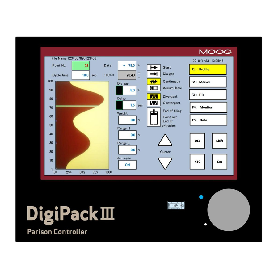
Moog DigiPack III J141-215 Installation, Maintenance And User Manual (89 pages)
Parison Wall Thickness Controller
Brand:
Moog
| Category:
Controller
| Size: 6 MB
Table of Contents
Table of Contents
5
1 Digipackⅲ Manual, Installation and Maintenance
10
Changes from J141-214A
10
Introduction
11
General Description
11
Figure 1-1 Digipackⅲ Appearance
11
Figure 1-2 Basic Continuous Blow Molding Machine Control Diagram
12
Figure 1-3 Basic Accumulator Machine Control Diagram
13
WHO CAN INSTALL the Digipackⅲ
14
Installation Time
15
Software Update
15
Figure 1-4 Start up Display
15
Backup Battery
16
SCREEN DISPLAY PROTECTION (Password)
16
DATA TRANSFER from Digipackⅱ
16
Digipackⅲ SPECIFICATION
17
Check List
18
Installation Check List
18
Mechanical Installation
19
General
19
Figure 1-5 die Gap Tooling Actuator Installation
19
Figure 1-6 die Gap Tooling Actuator
19
Tooling Adjustment
20
Figure 1-7 Actuator - die Gap Tooling Mechanical Adjustment
20
Figure 1-8 Tooling Adjustment Mechanism
20
Moog die Gap Tooling Actuators
21
Cylinder Installation
21
Figure 1-9 Typical Cylinder Installation
21
Customer Supplied Cylinder Requirements
22
Figure 1-10 G631-XXX Servovalve
22
Tooling Adjustment
23
Accumulator Position Measurement
23
Figure 1-11 Typical Linear Potentiometer
23
Figure 1-12 Lwhxxx Potentiometer Installation
23
The Importance of Filtration
24
Filter Installation
24
Figure 1-13 High Pressure Filter
24
Hydraulic Power Supply
25
Hydraulic Power Supply Start up Instructions
25
Figure 1-14 Hydraulic Power Supply
25
Contamination Control
26
Figure 1-15 Flow Pressure Filter
26
Electrical Installation
27
General
27
Rear Connector
27
Figure 1-16 REAR CONNECTOR
27
Wiring
28
Communication and Ssi Snsor Wiring
28
Figure 1-17 Digipackⅲ Installation Drawing
29
Figure 1-18 Servovalve and Transducer Phasing
30
Figure 1-19 TB-1 Connections
30
Figure 1-20 TB-1 Functions
31
Figure 1-21 TB-2 Connection
32
Figure 1-22 TB-2 Connection
32
Figure 1-23 TB-2 Functions
33
I/O Circuitry
34
Figure 1-24 Input Use External Power Supply
34
Figure 1-25 Input Use Internal Power Supply
34
Figure 1-26 Output Use External Power Supply
34
Figure 1-27 Output Use Internal Power Supply
34
Tb-3: Power Supply
35
Noise and Ground Isolation
35
Moog 2019 IV Mrj06301
35
Figure 1-28 Power Supply Connections
35
Figure 1-29 Accumulator Machine Timing Chart
36
Figure 1-30 Continuous Machine Timing Chart
37
Calibration of Touch Screen
38
Figure 1-31 Touch Screen Calibration
38
Figure 1-32 Touch Screen Calibration Display
38
Digipackⅲ Front Panel
39
Figure 1-33 Digipackⅲ Flont Panel
39
Tooling System Setup
41
General of Setup
41
Machine Setting
41
Figure 1-34 Machine Setup Display (SHIFT→F4)
42
Figure 1-35 Machine Setting Functions
42
Figure 1-36 Example of Profile Points Change
43
Set up Procedure
44
Figure 1-37 Setup Screen
44
Figure 1-38 die Converge/Diverge Setup
44
Figure 1-39 die Gap Setup
45
Figure 1-40 DCDT Noise Filter
45
Figure 1-41 die Gap Span Setting
46
Figure 1-42 Back
47
Figure 1-43 Gain Select
48
Figure 1-44 Gain Setting
48
Figure 1-45 Accumulator Setup
49
Figure 1-46 EMPTY Accumulator Set up
49
Figure 1-47 FULL Accumulator Set up
50
Figure 1-48 Extrusion Fixed
50
Figure 1-49 Filling Fixed
50
Figure 1-50 Accumulator Setting (Back)
51
2 Digipackⅲ Manual, User Operation
52
Introduction
52
Figure 2-1 Digipackⅲ Appearance
52
Parison Control
53
History
53
Parison Programming Benefits
53
Continuous Extrusion Machines
53
Accumulator Machines
53
Parison Programming Benefits
54
Figure 2-2 Section of an Un-Programmed Parison and the Resulting Container Walls
54
Figure 2-3 Section of a Programmed Parison and the Resulting Container Walls
54
With Accumulator Blow Molding Machines
55
With Continuous Blow Molding Machines
55
Parison Mold Alignment
56
Figure 2-4 Poor Vertical Alignment between the Parison and the Mold
56
Figure 2-5 Good Vertical Alignment between the Parison and the Mold
56
Man Machine Interface
57
Operator Control
57
Input Function
57
Figure 2-6 Digipackⅲ Front Panel
57
Figure 2-7 Ten Key on the Screen (1)
58
Figure 2-8 Ten Key on the Screen (2)
58
Functions
60
State Monitoring Area
60
Edit Area
61
Figure 2-9 Status Indicator
61
Screens of Edit Area
62
Editing Method
62
Figure 2-10 F1: Profile Mode Screen
62
F1: Profile Mode
63
Figure 2-11 Profile Mode Screen
63
Figure 2-12 0%Weight Change
65
Figure 2-13 (-)23.3% Weight Change
65
Figure 2-14 0% Range H
66
Figure 2-15 (+)25.0% Range H Change
66
Figure 2-16 0% Range L
67
Figure 2-17 (-)20.0% Range L
67
F2: Marker Mode
68
Figure 2-18 Marker Mode Screen
68
Figure 2-19 Slope Timing
69
F3: File Mode
70
Figure 2-20 File Mode Selection Screen
70
Figure 2-21 Select SAVE
70
Figure 2-22 File Description Data
71
Figure 2-23 File Description Data-Page
71
Figure 2-24 File Description Data-Page
71
Figure 2-25 Edit File Name
72
Figure 2-26 Change File Number
72
Figure 2-27 Initial Load Screen
73
Figure 2-28 File Load
73
F4: Monitor Mode
74
Figure 2-29 F4: Monito Screen
74
F5: Data Display Mode
75
Figure 2-30 Data Display Screen a
75
Figure 2-31 Data Display Screen B
75
Figure 2-32 Data Display Screen C
75
SHIFT→F1: Set up Mode
76
SHIFT→F2: Analog Monitor
76
Figure 2-33 [SHIFT]→[F1]: Setup Screen
76
Figure 2-34 [SHIFT]→[F2]: Analog Monitor Screen
76
SHIFT→F3: File Delete and Backup/Restore
77
Figure 2-35 [SHIFT]→[F3]: File Delete and Backup
77
SHIFT→F4: Machine Setup
78
Figure 2-36 File Delete
78
Figure 2-37 [SHIFT]→[F4]: Machine Setup Screen
78
SHIFT→F5: Communication Mode
79
Figure 2-38 [SHIFT]→[F5]: Communication Mode Screen
79
Communication Protocol
80
Ethernet COMMUNICATION SPECIFICATION
80
Profile
80
Wave
82
Monitor
82
Information Data
82
Interface Control
83
Other
85
Error Code
85
Adc/Dac Channel
85
Profile Data List
86
Setting up
87
Objective
87
Die Gap Tooling Setup
87
Preliminary Set up
88
Initial Trials
89
Advertisement
Advertisement
Related Products
Moog IMI220-145D001
Moog DigiPack 2
Moog SYSTEM II
Moog SYSTEM III
Moog IRM7C2N
Moog IRM7T2N
Moog ISM5CN
Moog Infinity
Moog SView IFDP7CN-3
Moog FusionDome IFDP75CF2N
Moog Categories
Synthesizer
Control Unit
Servo Drives
Medical Equipment
Security Camera
More Moog Manuals
Login
Sign In
OR
Sign in with Facebook
Sign in with Google
Upload manual
Upload from disk
Upload from URL