Sign In
Upload
Manuals
Brands
MLC Manuals
Control Systems
LC100
User Manuals: MLC LC100 Elevator Control System
Manuals and User Guides for MLC LC100 Elevator Control System. We have
1
MLC LC100 Elevator Control System manual available for free PDF download: User Manual
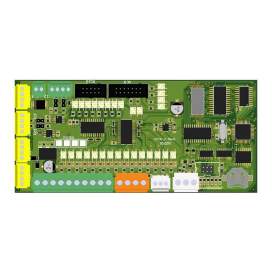
MLC LC100 User Manual (148 pages)
CAN bus microprocessor elevator system
Brand:
MLC
| Category:
Control Systems
| Size: 16 MB
Table of Contents
Table of Contents
2
General
4
LC100 Boards Description
5
LC100-C Main Control Unit
5
LC100-K Cabin I/O Board
8
LC100-K2 Cabin I/O Board
9
LC100-K3 Cabin I/O Board
10
LC100-S Safety Circuit Board
11
LC100-SR Safety Circuit Board
16
LC100-E Input-Output Unit for Cabin Calls
17
LC100-E2 In/Out Board
19
LC100-E3 Cabin I/O Board
21
LC100-E3.1 Cabin I/O Board
23
LC100-E4 Cabin I/O Board
24
LC100-E5 Cabin I/O Board
25
LC100-E6 Cabin/Landing I/O Board
27
LC100-F In/Out Board
28
LC100-D Control Terminal
29
LC100-D2 Control Terminal
30
LC100-Z Cabin Connection Board
31
LC100-R Relay Board with 4 Relays
34
LC100-T Relay Board with 8 Relays
35
LC100-I IN/OUT Board
36
Boards for Landing Calls and Signalization
38
LC100-M5 Dot Matrix Display
38
LC100-M7 Segment Display
40
Adressing the Landing Call Units (LC100-M Boards)
46
LC100-J Input/Output Board
47
LC100-V Load Measurement Board
49
LC100-V2 Load Measurement Board
50
LC100-B CAN Bridge Board
51
LC100-VFD - CAN Bridge Bord, Relay Output, Phase Control Bord
52
LC100-H CAN Connection Board
53
LC100-GSM Emergency Voice Call
54
LC100-HF Handsfree Voice Communication
55
Managment with LC100-D Terminal
56
Basic View
56
Basic Elevator State
57
Display of Current Elevator Station
57
Safety Line and Drive Display
58
Active Delays and Errors Display
59
Menu Structure
69
Statistics
70
Parameters
77
General - Type a
78
Call Processing - Type B
80
Main Drive - Type C
84
Doors - Type D
89
Positioning - Type E
95
Stopping - Type F
98
Lift Markings - Type G
98
Timers - Type H
98
Protection - Type I
102
Configurations - Type N
106
Output Function Table
107
Input Functions Table
111
Cabin Calls Side a Table
116
Cabin Calls Side B Table
116
P-M-L Modul - Type P
117
Factory - Type T
118
LC100 Menu
124
Date/Time
125
Info
125
Test Mode
126
Memory
126
Transfer
128
Lc100-D Additional Menu
129
General
129
Aditional Menu Structure
130
LC100-M5/M6/M7 Addressing
131
ADL 200/300 Parameters
132
CAN Bus Traffic Analysis
133
CAN2 Bus Elevator Select
134
Load Measurement
135
Utility
138
User Code
138
Elgo
138
Appendix 1. Positioning
139
Appendix 2. Traveling Cable Connection
143
Appendix 3. Connecting the Can and Can Bus Termination
144
Advertisement
Advertisement
Related Products
MLC LS12/2
MLC LS6
MLC LS10
MLC LS10/6
MLC Categories
Switch
Music Equipment
Control Systems
More MLC Manuals
Login
Sign In
OR
Sign in with Facebook
Sign in with Google
Upload manual
Upload from disk
Upload from URL