Table of Contents
Advertisement
Quick Links
Advertisement
Table of Contents

Summary of Contents for MLC LC100
-
Page 2: Table Of Contents
LC100-V load measurement board .................49 2.24 LC100-V2 load measurement board ...............50 2.25 LC100-B CAN bridge board ..................51 2.26 LC100-VFD - CAN bridge bord, relay output, phase control bord ......52 2.27 LC100-H CAN connection board ................53 2.28 LC100-GSM emergency voice call ................54 2.29 LC100-HF handsfree voice communication ............55... - Page 3 LC100 menu .........................124 Date/time ........................125 Info ..........................125 Test mode ........................126 Memory ..........................126 Transfer ..........................128 LC100-D ADDITIONAL MENU ................129 General ..........................129 Aditional menu structure .....................130 6.3 LC100-M5/M6/M7 addressing ..................131 ADL 200/300 parameters ....................132 6.5 CAN bus traffic analysis ....................133 6.6 CAN2 bus elevator select ..................134 6.7 Load measurement ....................135...
-
Page 4: General
1. General LC100 is a microprocessor control system for elevators up to 40 stops and 8 elevators in multiplex work. The system is universal and applicable to a wide variety of requirements that are set to control a new generation of all types of elevators up to 4m/s.. -
Page 5: Lc100 Boards Description
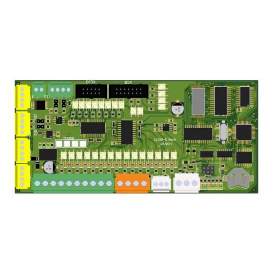
Picture 1 - Example of connecting the inputs. The example in Figure 1 shows a way of connecting the inputs on the LC100-C plate, the polarity configuration inputs (NO or NC) is available on all inputs through the configuration parameters TYPE-N. - Page 6 LC100 Instruction manual Picture 2 - LC100-C board Connection diagram for bimetal, ptc probe and inductive switch on overspeed governor:...
- Page 7 LC100 Instruction manual Power suply for LC100-C board:...
-
Page 8: Lc100-K Cabin I/O Board
LC100-K board is used as an input/output unit for elevator cabin. Suply is 24VDC and is powered via CAN / power connector XK1, XK2. All inputs and outputs on the LC100-K board are programmable. You can change the polarity of the inputs (NO or NC) and output (NOR or INV). -
Page 9: Lc100-K2 Cabin I/O Board
Suply is 24VDC and is powered via CAN / power connector XK1, XK2, XK3 All inputs and outputs on the LC100-K2 board are programmable. You can change the polarity of the inputs (NO or NC) and output (NOR or INV). -
Page 10: Lc100-K3 Cabin I/O Board
Suply is 24VDC and is powered via CAN / power connector XK1, XK2, XK12. All inputs and outputs on the LC100-K3 board are programmable. You can change the polarity of the inputs (NO or NC) and output (NOR or INV). -
Page 11: Lc100-S Safety Circuit Board
LC100 Instruction manual LC100-S safety circuit board LC100-S safety board is used to connect elements of a safety circuit. Information about points of safety circuit is transfered to lower voltage through optocoupler and then transfered through XS15 flat connector to main LC100-C board. - Page 12 LC100 Instruction manual On LC100-S board there are also connectors for connecting the drive shaft light with LED indicator and controling the status for automatic control of the light (the light is powered automaticly when the inspection mode is on). Shaft lighting is controled by relay RL1 with output parameter XC10.2.
- Page 13 LC100 Instruction manual XS27 connector is a power supply 230VAC for cabin, XS26 connector is output power suply for the cabin connected with the traveling cable. Cabin power supply connection diagram:...
- Page 14 LC100 Instruction manual Connectors XS20 to XS23 are use to connect to a voice device in the cabin, emergency power supply, alarm buttons, and indicator "elevator in the station " XS20 output connector is used for connecting "elevator in the station " indicator, and connecting safety module for aplications whith releveling or preopening the doors..
- Page 15 LC100 Instruction manual Picture 5 - LC100-S bord...
-
Page 16: Lc100-Sr Safety Circuit Board
LC100 Instruction manual LC100-SR safety circuit board LC100-SR safety board is used to connect elements of a safety circuit. Information about points of safety circuit is transfered to lower voltage through optocoupler and then transfered through XS3 flat connector to main LC100-C board. -
Page 17: Lc100-E Input-Output Unit For Cabin Calls
LC100-E input-output unit for cabin calls LC100-E board of the system is used as input / output unit. The main purpose of the board is for cabin call processing. It consists of CAN communication connector XE1 and XE2,and connectors with I / O pins and XE3 XE4. - Page 18 LC100 Instruction manual Picture 4 - LC100-E board...
-
Page 19: Lc100-E2 In/Out Board
LC100-E2 in/out board LC100-E2 board of the system is used as input / output unit. The main purpose of the board is for cabin call processing. It consists of CAN communication connector XE1 and XE2,and connectors with I / O pins XE3 XE4. - Page 20 LC100 Instruction manual Picture 6- LC100-E2 board...
-
Page 21: Lc100-E3 Cabin I/O Board
LC100-E3 cabin I/O board LC100-E3 board of the system is used as input / output unit. The main purpose of the board is for landing and cabin call processing. It consists of CAN communication connector XE1 and XE2,and connector with I / O pins XE3 and XE4. - Page 22 LC100 Instruction manual Picture 7- LC100-E3 board...
-
Page 23: Lc100-E3.1 Cabin I/O Board
2.10 LC100-E3.1 cabin I/O board LC100-E3.1 board of the system is used as input / output unit. The main purpose of the board is for landing and cabin call processing. It consists of CAN communication connector XE3 and XE4,and connector with I / O pins and XE5 with parallel connection to XE6 and XE7 connector for managment relays. -
Page 24: Lc100-E4 Cabin I/O Board
2.11 LC100-E4 cabin I/O board LC100-E4 board of the system is used as input / output unit. The main purpose of the board is for landing and cabin call processing and for inputs/outputs. It consists of CAN communication connector XE1 and XE2,and connector XE3 and XE4 with I / O pins and XE6 output connector and XE5 input connector. -
Page 25: Lc100-E5 Cabin I/O Board
2.12 LC100-E5 cabin I/O board LC100-E5 board of the system is used as input / output unit. The main purpose of the board is for landing and cabin call processing. It consists of CAN communication connector XE1 and XE2,and connector with I / O pins XE3 and XE4. - Page 26 LC100 Instruction manual Picture 10- LC100-E3 board...
-
Page 27: Lc100-E6 Cabin/Landing I/O Board
2.13 LC100-E6 cabin/landing I/O board LC100-E6 board of the system is used as input / output unit. The main purpose of the board is for landing and cabin call and output for driving display. It consists of CAN communication connector X1 and X2, and connector X3 I / O pins and X4 output connector through relays. -
Page 28: Lc100-F In/Out Board
To LC100-K board is possible to connect two LC100-F boards with adress „C“ and „D“, to LC100-E0 board is possible to connect two board with adress „C“ and „D“, and to LC100-E1 board is possible to connect two boards with adress „C“... -
Page 29: Lc100-D Control Terminal
LC100 Instruction manual 2.15 LC100-D control terminal LC100-D control terminal consists of a 2x16 blue LCD screen to display and push-button ENTER, ESC, left, right, up and down navigation and push-button to reset the system. Reset button is used for reseting some errors that can't be reset by recycling the power. By pressing the reset button for 5s procesor is reseted like switching the power of and on. -
Page 30: Lc100-D2 Control Terminal
LC100 Instruction manual 2.16 LC100-D2 control terminal LC100-D2 control terminal consists of a LCD screen to display and push-button ENTER, ESC, left, right, up and down navigation and push-button to reset the system and function buttons F1, F2, F3, F4, download. -
Page 31: Lc100-Z Cabin Connection Board
Dimensions of plate are 229x72mm and mounting is done on TS35 rail using bracketplates or with spacers. (there are holes on the modul). Management of relays on the plate is carried out through input connector XZ20 which connects with LC100- K XK9 output connector. Next to each relay is a status LED indication. - Page 32 Safety circuit on the cabin connection diagram: LC100-Z circuit includes an emergency power supply. Circuit for emergency power supply is equipped with a 100mA fuse on the primary side of transformer, and 1A fuse on the side of the 12VDC power supply. On the board is installed potentiometer for setting the battery charging voltage.
- Page 33 LC100 Instruction manual Picture 14 - LC100-Z board...
-
Page 34: Lc100-R Relay Board With 4 Relays
2.18 LC100-R relay board with 4 relays LC100-R is relay circuit board with 4 relays. Management of relays is performed through the 10 pin flat connector XR1 which is connected to XC10 or XK9 connector, managment of relays is also possible through XR2 connector. -
Page 35: Lc100-T Relay Board With 8 Relays
2.19 LC100-T relay board with 8 relays LC100-T is a relay board with 8 relays. Management of relays is performed through the 10 pin flat connector XT1 which is connected to XC10 or XK9 connector. When relays are powered trough XC10 or XK9 connector then on the board are 6 relays. -
Page 36: Lc100-I In/Out Board
LC100 Instruction manual 2.20 LC100-I IN/OUT board LC100-I is input-output board used mainly on elevators whithout mashine room when there is a control cabinet in the shaft. LC100-I consist of : 8 digital input connected to connector XI3 4 relay output connected to XI4... - Page 37 LC100 Instruction manual Picture 17 - LC100-I board...
-
Page 38: Boards For Landing Calls And Signalization
LC100-M5R Red dot display LC100-M5 displays are used as landing displays with connector for connecting the landing calls. Connection to the displays is made trough XC12 connector which is CAN2 bus. Each display is addressed for a floor. Addressing is done through the aditional menue for addressing. - Page 39 LC100-M6R Red dot display LC100-M6 displays are used as landing displays with connector for connecting the landing calls. Connection to the displays is made trough XC12 connector which is CAN2 bus. Each display is addressed for a floor. Addressing is done through the aditional menue for addressing.
-
Page 40: Lc100-M7 Segment Display
LC100-M7R Red 7-segment display LC100-M7 displays are used as landing displays with connector for connecting the landing calls. Connection to the displays is made trough XC12 connector which is CAN2 bus. Each display is addressed for a floor. Addressing is done through the aditional menue for addressing. - Page 41 Red DOT matrix display LC100-M3 displays are used as a cabin displays and can be used as a landing units. When used as a cabin display it is connected to CAN1 bus, and used as a landing call units it is connected to CAN2 bus (connector XC12).
- Page 42 Red DOT matrix display LC100-M8 displays are used as a cabin displays and can be used as a landing units. When used as a cabin display it is connected to CAN1 bus, and used as a landing call units it is connected to CAN2 bus (connector XC12).
- Page 43 2.21.6 LC100-L1 TFT display LC100-L1 displays are used as landing displays with connector for connecting the landing calls. Connection to the displays is made trough XC12 connector which is CAN2 bus. Each display is addressed for a floor. Addressing is done through the aditional menue for addressing.
- Page 44 LC100-L2 TFT display LC100-L2 displays are used as a cabin displays and can be used as a landing units. When used as a cabin display it is connected to CAN1 bus, and used as a landing call units it is connected to CAN2 bus (connector XC12).
- Page 45 LC100-L3 TFT display LC100-L3 displays are used as a cabin displays and can be used as a landing units. When used as a cabin display it is connected to CAN1 bus, and used as a landing call units it is connected to CAN2 bus (connector XC12).
-
Page 46: Adressing The Landing Call Units (Lc100-M Boards)
LC100 Instruction manual 2.22 Adressing the landing call units (LC100-M boards) Adressing is done with microswitches on the landing calls units (LC100M boards). Switches S1 to S6 are used for adressing landing units, adressing is binary coded given in the table. -
Page 47: Lc100-J Input/Output Board
LC100 Instruction manual 2.23 LC100-J input/output board LC100-I board is used as aditional input/output board. It is equipped with 8 in/out ant two CAN connectors. There are also microswitches for addressing or defining functions acordint to the instaled software. Picture 26 - LC100-J board Aplications examples using LC100-J board: 1. - Page 48 2. Floor units DUPLEX elevator with „C“ i „D“ protocol displays. Floor units are coded acording to the addressing table. LC100-J boards are connected to CAN2 bus, there is no need for parameterization because inputs and outputs are set as shown on the connection diagram.
-
Page 49: Lc100-V Load Measurement Board
LC100 Instruction manual 2.24 LC100-V load measurement board LC100-V board is used to connect the load measurement cells. It has four connectors for connecting up to four cells and a flat connector for connecting it to the LC100-K board. Programming the load measurement is done with the LC100-D2 keyboard as explained in additional menu, section... -
Page 50: Lc100-V2 Load Measurement Board
LC100 Instruction manual 2.25 LC100-V2 load measurement board LC100-V2 board is used to connect the load measurement cells. Programming the load measurement is done with the LC100-D2 keyboard as explained in additional menu, section 5/7 LOAD MEASUREMENT Picture 28 LC100-V2 board... -
Page 51: Lc100-B Can Bridge Board
LC100 Instruction manual 2.26 LC100-B CAN bridge board LC100-B CAN bridge board is used for connecting can devices which are not compatible with the LC100 CAN protocol (frequency inverter, encoders…). Board is connected to CAN1 bus of LC100 trough XB1 or XB2 connector. -
Page 52: Lc100-Vfd - Can Bridge Bord, Relay Output, Phase Control Bord
2.27 LC100-VFD - CAN bridge bord, relay output, phase control bord LC100-VFD – bord include CAN bridge (CAN bridge board is used for connecting can devices which are not compatible with the LC100 CAN protocol (frequency inverter)), 4 relay outputs, phase control, display which show elevator direction and speed. -
Page 53: Lc100-H Can Connection Board
LC100 Instruction manual 2.28 LC100-H CAN connection board LC100-H board is used to multiply CAN connectors, it consist of 4 CAN conectors. LC100-H board connection: Picture 31 - LC100-H board... -
Page 54: Lc100-Gsm Emergency Voice Call
LC100 Instruction manual 2.29 LC100-GSM emergency voice call LC100-GSM is GSM modem bord used for emergency voice calls and communication with Lift Remote Monitoring system. Main functions: 2 independent CAN BUS serial communication channels Integrated GSM/GPRS modem with SIM card slot... -
Page 55: Lc100-Hf Handsfree Voice Communication
LC100 Instruction manual 2.30 LC100-HF handsfree voice communication LC100-HF is bord with handsfree voice communication function (part of emergency voice communication system). Main functions: CAN bus serial communication Alarm enable and alarm pushbutton connection Integrated speaker and microphone Fully digital voice transfer via CAN BUS (excellent noise immunity and acoustic echo cancellation) „0219-E-ENG-LC100_Emergency_Telephone_Manual.pdf“... -
Page 56: Managment With Lc100-D Terminal
3.1 Basic view The main display on the LC100-D terminal contains basic status of the system. Display status is divided into 6 parts: 1. The basic state status 4. -
Page 57: Basic Elevator State
LC100 Instruction manual 3.1.1 Basic elevator state Basic elevator state is shown on the top line on the primary screen of terminal LC100-D. Elevator state Description Indicates that the service travel port is not defined FI-235. It is necessary to define service travel port in configuration. -
Page 58: Safety Line And Drive Display
LC100 Instruction manual 3.1.4 Safety line and drive display In standby (with no calls) last five characters of second line indicates the status of controlled points in safety circuit: Indicates acive state Indicates inactive state First field indicates the presence of safety circuitvoltage at the terminal... -
Page 59: Active Delays And Errors Display
Elevator state Description Indicates that the voltage is switched on. Indicates that the reset button is pressed on the LC100-D keyboard or reset input is active. Indicates that the inputs are active at the same time for button service travel... - Page 60 LC100 Instruction manual Indicates that the 80% load input is activated (input with parametar FI-241) more than 10 sec. Elevator ignores landing calls. Indicates that the 100% load input in activated (input with parametar FI-242) more than 10 sec. Elevator stays at the station with open door.
- Page 61 LC100 Instruction manual Safety circuit state messages: Screen message Description Indicates that safey circuit is interrupted before the first series of control points on the connector XS8:3, or power circuit interruption between connectors XS1:1 and XS8:3 Indicates that safety circuit is interrupted at the landing door contact. No power on connector XS9:2 Indicates that safety circuit is interrupted at the car door A contact.
- Page 62 20%. After activating the error it is necessary to reset the control disconnecting power supply or using the reset button on LC100-D terminal. Inspection travel is possible. Indicates that the elevator after start from the station has not moved for logner that the time set by parameter I-03.
- Page 63 Since the above error may occur as a result of copying error (stopping switch) elevator must do a first travel again. It is necessary to reset the control disconnecting power supply or using the reset button on LC100- D terminal.
- Page 64 LC100 Instruction manual Screen messages Description Indicates an obstacle signal too long (>30s) while closing door A FI-262. The message is information about input state, elevator is holding the door open until signal deactivation. Function is off during inspection travel.
- Page 65 LC100 Instruction manual Elevator positioning error messages: Screen messages Description Elevator stopped at the station, 1st station copied, and the lower reference switch not activated FI-252. Elevator repeats learning travel. Error is effective for the copy type E-01=2 Possible errors: Too many stations copied so elevator stopped in the station without reference switch.
- Page 66 FI-300. Fault can't be reset with reseting the power. Fault must be reset with the reset button on the LC100-D keypad. If service drive is switched on than controller will give a reset command on the first inspection drive command is reseting is possible.
- Page 67 Control of the overspeed governor contactor is done trough the input with the function FI-291. Fault must be reset trough reset button on the LC100-D2 keypad. Indicates that when stopping the elevator overspeed governor contactor was not powered off. Control of the overspeed governor contactor is done trough the input with the function FI-291.
- Page 68 – address 0. Communication error between LC100-C with LC100-E board with – address 1. Communication error between LC100-C with LC100-C board of elevator – „A“ in duplex mode. Communication error between LC100-C with LC100-C board of elevator – „B“ in duplex mode.
-
Page 69: Menu Structure
LC100 Instruction manual 3.2 Menu structure 1/6 Statistics 1/4 ACT.ERRORS 2/6 Monitor 1/2 Input/Output 2/4 ALL ERRORS 3/6 CALLS 2/2 CAN status 3/4 Analysis err 1/12 GENERAL type A 4/4 COUNTERS Parameters 5/6 LC100 2/12 Call processing type B 3/12 Main drive... -
Page 70: Statistics
LC100 Instruction manual 3.2.1 Statistics 1/6 Statistics Active errors Active error Floor Number of error Message ID Time when error apeared Active errors menu displays active errors. In the first row error is displayed. Means number of error. The last error is the one with number 0, the one before is number 1 and so on. - Page 71 LC100 Instruction manual 1/6 Statistics Counters In „Counter“ menu there are few counters. After entering the menu „total counter is shown. Pressing the left or right button it is possible to chose user counter, daily counter, monthly counter and annual counter.
- Page 72 Input/output menu is used to monitor status of the inputs-outputs of all boards in the system. First row shows the LC100 board. Second row displays connector, third row displays pin on the connector. In the fourth row under the pin sign...
- Page 73 LC100-F board adress „D“ is included through parameter A-08. Status of the input/output signals on LC100-P, M or L boards for pins 2 and 3 on connector XP3 or XM3. A-10 means first ten adreses of P or M boards on side „A“.
- Page 74 LC100 Instruction manual Status of the input/output signals on LC100-P, M or L boards for pins 2 and 3 on connector XP3 or XM3. A-20 means second ten adreses of P or M boards on side „A“. Second row presents floor 1=adress 11, 2=adress 12, ond so on.
- Page 75 2/6 Monitor CAN status In CAN status menu it is posible to see status of communication between main control board LC100-C with other LC100 units connected to CAN bus. After entering the menu communication with LC100-I, K, E0 and E1 board is displayed.
- Page 76 LC100 Instruction manual 3.2.3 Calls 3/6 Calls In the calls menu it is possible to monitor cabin and landing calls. It is also possible to assign a cabin call. First row is reserved for monitoring the calls from first ten floors.
-
Page 77: Parameters
LC100 Instruction manual 4. Parameters Menu parameters is used for monitoring and setting parameters of the LC100 system. Viewing the parameters is possible without password while to change the values of parameters password is needed. Parameters are divided into 12 submenus:... -
Page 78: General - Type A
2 – manual evacuation by pressing the brake open button from the cabin. Configuration LC100 Parameter to include the LC100-I, LC100-VFD, LC100-Y, LC100-SR board into system. If there exist board connected to CAN bus it needs to be included through parameter. - Page 79 Type A Configuration LC100 Parameter to include the LC100-K, LC100-K2, LC100-V, LC100-V2 bord into system. If there exist bord connected to CAN bus it needs to be included through A-6 parameter. Including is done by placeing the sign „ “ under the „board“...
-
Page 80: Call Processing - Type B
Parameter to include LC100-E4 board into the system. Including is done by placeing the sign „ “under the „board“ character. (list below) 0 – LC100-E4 (address 0) 1 – LC100-E4 (address 1) 2 – LC100-E4 (address 2) 3 – LC100-E4 (address 3) - Page 81 LC100 Instruction manual 4/6 Parameters 2/12 Call processing Type B Program A/B side Program A/B side 0 – Cabin doors are opened according to the parameters for door side (D-02 to D-11) independently to landing call side. (ex. if in the 2nd floor has two doors...
- Page 82 LC100 Instruction manual 4/6 Parameters 2/12 Call processing Type B B-10 Fire stop zone 4 0-A1 Defining the floor for evacuation in case of fire program 3. Fire program 3 is activated through the input with the function parameter FI-212.
- Page 83 LC100 Instruction manual 4/6 Parameters 2/12 Call processing Type B B-15 Parking stop 2 0-A1 Setting the parking stop 2. 0 – Not activated – parking program is not active. 1-A1 – Parking floor. After the time set in the parameter...
-
Page 84: Main Drive - Type C
LC100 Instruction manual Main drive - Type C 4/6 Parameters 3/12 Main drive Type C Main drive type Parameter is used for defining the main drive type. 1 –Not regulated AC1 – One speed elevator. When the drive is one speed... - Page 85 LC100 Instruction manual 4/6 Parameters 3/12 Main drive Type C Leveling speed Parameter is used to set speed encoding for relevelling speed. Parameter is available only for frequency regulated elevators (C-01=3). Sign „ “ under a specific letter means that in relevelling speed board activates the outputs with the belonging parameter.
- Page 86 LC100 Instruction manual 4/6 Parameters 3/12 Main drive Type C Inspection speed 2 0-2,5s Parameter is used to set speed encoding for inspection speed 1. Parameter is available only for frequency regulated elevators (C-01=3). Sign „ “ under a specific letter means that in intermidiate speed board activates the outputs with the belonging parameter.
- Page 87 LC100 Instruction manual 4/6 Parameters 3/12 Main drive Type C C-15 Service speed Setting the command for service speed. 0 – Service speed is done with low speed ( function FO-03) 1 – Service speed is done with high speed ( function FO-04) Parameter is active only for C-01=2 or 4, while for one speed elevators it must be set to „1“...
- Page 88 LC100 Instruction manual 4/6 Parameters 3/12 Main drive Type C C-20 Open brake time on evacuation 0-2,5s Parameter is used for setting the „on“ time of output function FO-36. C-21 Close brake time on evacuation 0-2,5s Parameter is used for setting the „off“ time of output function FO-36.
-
Page 89: Doors - Type D
LC100 Instruction manual Doors - Type D 4/6 Parameters 4/12 Door Type D Cabin door Cabin door type selection: 0- No door or manual door 1- One automatic cabin door 2- Two automatic cabine doors In the case of two cabin doors, door opening in the stations must be defined... - Page 90 LC100 Instruction manual 4/6 Parameters 4/12 Door Type D D-12 A-side door orders Voltage holding definition (command open or close active) for cabin door at A-side. A – Close door output FO-41 is active during travel. B – Open door output FO-40 is active during passanger passing time.
- Page 91 LC100 Instruction manual 4/6 Parameters 4/12 Door Type D Door A open D-17, D-18, D-19 D-17 - same as D-16 but for stations 17 to 24 D-18 - same as D-16 but for stations 15 to 32 D-19 - same as D-16 but for stations 33 to 40...
- Page 92 LC100 Instruction manual 4/6 Parameters 4/12 Door Type D B-side automatic door open in stations 9 to 16 D-24 Defining stations in which elevator waiting with door B open. For stations 9 to 16. Parameter has function with automatic landing door B D-14=1 or 3.
- Page 93 LC100 Instruction manual 4/6 Parameters 4/12 Door Type D Passenger passing time after cabin call D-32 0-25s Passenger passing time after new cabin call while in station. By giving new cabin command passenger passing time is set by parameter. Door deceleration time...
- Page 94 LC100 Instruction manual 4/6 Parameters 4/12 Door Type D Error detection light curtain (EN81-20) D-39 0-250 Parameter is used to enable/disable light curtain error detection. Detection works on way that look input FI -263/FI-273 and cabin calls. If they have cabin call and don’t have active inputs more seted value.
-
Page 95: Positioning - Type E
LC100 Instruction manual Positioning - Type E 4/6 Parameters 5/12 Positioning Type E E-01 Positioning type Choosing the positioning type: 1 – Positioning type for one speed elevator. For positioning type 1 referent switches are used and stopping switch is used. Elevator is driving with one speed, floors are counted when passing through stop switch according to the driving direction. - Page 96 LC100 Instruction manual 4/6 Parameters 5/12 Positioning Type E E-04 Preopening speed [imp/s] 0-100imp Parameter is used as a speed control for preopening the doors. Speed is measured by the number of impulses on the inductive switch (positioning type E-01=4 or 5). If the speed is lower than one defined in the parameter E-04 then output with the „preopening enabled“...
- Page 97 LC100 Instruction manual 4/6 Parametri 5/12 Kopiranje Tip E E-12 Decelerating distance for speed V2 [imp] 1.00-3.00 Parameter is used for positioning type 5. E-12 represent the decelerating zone for V2. If there is an input for second referent switch...
-
Page 98: Stopping - Type F
G-02 for second… In order to LC100-M board showing the floor marking it is needed to set PML parameters ( put „ “ sign under the letter „A“ for floors in which is the LC100- M board). - Page 99 LC100 Instruction manual 4/6 Parameters 8/12 Timers Type H H-03 Car light control type Car light control type selection. 1 – Standard – Function for controling the cabin light FO-51 is switched off afert time set in H-04 expired. 2 – Reserved.
- Page 100 If the photocell input is active longer than the time set by parameter, it is saved in the statistic and signaled on display. For display LC100-M or L to signalize photocell activity PML parameters must be set (mark „ “ below letter “I“ for stations with LC100-M or L display). H-13 CLOSING OBSTACLES signal activation...
- Page 101 LC100 Instruction manual 4/6 Parameters 8/12 Time Type H H-16 Save energy mode Parameter is used for switching on the power saving mode. In the power saving mode after time set in parameter H-17 all the displays are switched off...
-
Page 102: Protection - Type I
LC100 Instruction manual Protection - Type I 4/6 Parameters 9/12 Protection Type I 0-9999 I-01 Cold state PTC resistance Cold state PTC resistance. When the resistance of the PTC probe connected to the input XC8:2 rises above the value defined by parameter... - Page 103 LC100 Instruction manual 4/6 Parameters 9/12 Protection Type I I-07 Maximal time for door opening 0-25s Maximal time for opening the doors. When the end switches for the doors are used (FI-260 or FI-270) opening signal is active until door open signal is active.
- Page 104 LC100 Instruction manual 4/6 Parameters 9/12 Protection Type I I-12 Temperature for switching the control board fan ON 0-85°C Parameter for setting the temperature for control board fan. If the procesor temperature reaches the set value the output with the function FO-35 switched on.
- Page 105 LC100 Instruction manual I-16 Conditions mode A – not selected - stay in the station with opened doors don’t accept calls after detection UPS error. selected - enable automatic drive after detection UPS error. B – not selected - stay in the station with opened doors don’t accept calls after detection cabin light error.
-
Page 106: Configurations - Type N
4.10 Configurations - Type N 4/6 Parameters 10/12 Configurations Type N Configurations menu is for programing the input and output pins of LC100 boards. Example of configuring pin XC6:1 to have a function „program recall“: Pin to which the Status of the input/output: parameter is set. -
Page 107: Output Function Table
LC100 Instruction manual OUTPUT FUNCTION TABLE DYSPLAY ON LC100-D DESCRIPTION FO-001 Up travel command. FO-002 Down travel command. FO-003 Slow speed travelling command. FO-004 High speed travelling command. FO-005 Inspection speed travelling command. FO-006 Leveling speed travelling command. FO-007 Medium speed travelling comand. - Page 108 LC100 Instruction manual DYSPLAY ON LC100-D DESCRIPTION FO-031 End of fire program function. Function is on when fire program has ended. Function for controlling the shaft light. Function is on when inspection drive is FO-032 on, and turned off when turned back to normal drive and time H-05 expired.
- Page 109 Output function, active when door B is opened. Output function pulsating 1s „on“ 1s „off“ FO-078 Output function for reset, active when reset button on LC100-D keypad is FO-079 pressed. Cabin position output – binary code bit 0. It is used for car position...
- Page 110 LC100 Instruction manual DYSPLAY ON LC100-D DESCRIPTION FO-095 Nudging output for door A. FO-096 Nudging output for door B. Output function for start safety procedure for inspection drive in case of low FO-097 pit function (FI-308) didn’t occurred before switched off power supply.
-
Page 111: Input Functions Table
Input function for elevators with short safety space. After the input is once FI-206 activated (input FI-206) elevator is blocked until reset button on the LC100- D2 is pressed or activation of input FI-327 Input function for emergency passanger evacuation. After the input is active... - Page 112 Safety circuit control input for LANDING DOOR when LC100-S board not FI-231 used. FI-232 Safety circuit control input for DOOR A when LC100-S board not used. FI-233 Safety circuit control input for DOOR B when LC100-S board not used. Safety circuit control input for LANDING LOCK when LC100-S board not FI-234 used.
- Page 113 LC100 Instruction manual DYSPLAY ON LC100-D DESCRIPTION FI-258 Input for stopping zone switch. FI-259 FI-260 Opening limit switch input for door A FI-261 Closing limit switch input for door A FI-262 Input for closing door obstacle side A FI-263 Input for photocell door A FI-264 Input for door A open pushbutton.
- Page 114 Aditional input function for elevator with short pitt . After input FI-293 is active FI-293 elevator is blocked until reset on the LC100-D keypad or activating FI-372. Function is identical as function FI-206. Input for open door button for both cabin doors „A“ and „B“ FI-294 Input for close door button for both cabin doors „A“...
- Page 115 LC100 Instruction manual DYSPLAY ON LC100-D DESCRIPTION FI-334 Shaft light control input function. FI-335 Information input Alarm button is pressed. FI-336 Control input for light curtain of door A. FI-337 Control input for light curtain of door B. FI-338 Control input for temperature of door A.
-
Page 116: Cabin Calls Side A Table
LC100 Instruction manual CABIN CALLS SIDE A TABLE DYSPLAY ON LC100-D DESCRIPTION Cabin call A side for 1st floor. Cabin call A side for 2nd floor..Cabin call A side for 40th floor. Landing call up A side for 1st floor. -
Page 117: P-M-L Modul - Type P
In the PML modul menu it is possible to set the work of the signalization modules LC100-P, LC100-M or LC100- L. Sign „ “ under the letter means that for that module is activated mode which is explained in the description:... -
Page 118: Factory - Type T
LC100 Instruction manual 4.12 Factory - Type T 4/6 Parameters 12/12 Factory Type T T-01 Standard Parameter for choosing the standard for software. 1 – EN81 standard 2 – Russian standard (firefighter mode) When in firefigihter mode open cabin doors, elevator stay with opened doors until new call. - Page 119 1 – off parameter filtering is switched on. When the filtering is switched off all parameters of the system are visible through the LC100-D terminal. When the filter is „on“ parameters and functions are visible according to each other. If some parameters are not reacheable that means the filter is „on“.
- Page 120 Bin=1 – first station start with binary 0000 Gry=1 – standardy gray code output Gry=2 – shifted gray code output (Turkey market) T-13 Simulator enable Enable possibility to show simulator mode in LC100 menu. T-14 Control times valve down A3 0-2,50 s T-15...
- Page 121 (For other positioning type – descent length was determined by the T-18 x 100 ms) T-19 LC100-VFD configuration A – enable phase control through LC100-VFD card B – enable evacuation detection through LC100-VFD card (only in combination with selected letter A) C – Reserved D – Reserved E – Reserved F –...
- Page 122 LC100 Instruction manual T-20 Factroy settings A – not selected – Cabin door will be open in the fire station when fire program are active. selected – Cabin door will closing automatically after 60 sec in the fire station when fire program are active.
- Page 123 LC100 Instruction manual T-25 0-9999 Password 2 Set protection password level 2 for locking menu. If password is seted, on system booting must be entered password. If you don’t use keypad more then 10 min. system is automatically locked, to disable password put factory value 0000.
-
Page 124: Lc100 Menu
LC100 Instruction manual 5. LC100 menu LC100 menu has 7 submenus like shown on the picture: 5/6 LC100 1/7 Date/time 2/7 Info 3/7 Test mode 1/4 Montage drive 4/7 Memory 2/4 Drive 1 <-> A-1 3/4 Drive N <-> N+1... -
Page 125: Date/Time
After entering the menu setting is done by pressing the enter button. Changes are made with up, down, left or right button. Saving the changes is done by pressing the enter button. Info 5/6 LC100 Info Info menu shows the current software version installed at LC100-C board. -
Page 126: Test Mode
Montage drive presents driving the elevator without the cabin connection box (only with the contol cabinet in the machine room). If there is no cabin board LC100-K connected there is „Comm err with –K“ error – communication error with the LC100-K board. - Page 127 LC100 Instruction manual Reset 5/6 LC100 Reset In the reset menu it is possible to reset statistics, countersand parameters. After entering the menu type of reset is chosen by pressing left or right button. After choosing the reset, press enter button, then press left or right and confirm with the enter button.
-
Page 128: Transfer
Transfer 5/6 LC100 Transfer In transfer menu it is possible to transfer parameters from LC100-C board to the internal memory of LC100-D keypad. When enter the transfer menu chose direction for transfer parameters, after confirm there are 4 memory locations available , after choosing memory location confirm with enter button. -
Page 129: Lc100-D Additional Menu
When LC100-D is connected to a CAN bus where no LC100-C is present, the additional menu root will be brought up automatically. This behavior is useful for addressing signalization modules without connecting them to an elevator or analyzing CAN traffic on a bus that has no LC100-C connected to it e.g. standalone signalization module. -
Page 130: Aditional Menu Structure
LC100 Instruction manual Aditional menu structure 1/8 Addressing 1/3 Installed 2/8 ADL 200 2/3 Standalone 3/8 CAN Analysis 1/2 Trafic 3/3 DUPLEX 2/2 Errors 4/8 CAN2 elevat. 5/8 Load cell 1/7 Status 2/7 Zero load 6/8 Utility 3/7 Ref. load... -
Page 131: Lc100-M5/M6/M7 Addressing
By pressing and holding RESET key for more than 3 seconds, all signalization modules will be reverted to the default address (stop 0 i.e. cab indicator). Image on the left shows LC100-D screen when stop 12, elevator B and landing door A is selected. -
Page 132: Adl 200/300 Parameters
As long as LC100-D is in any one of the addressing modes, all of the connected dot-matrix signalization modules will display their assigned address via two interchanging screen images. One of them displays stop number and the other one displays two characters, left one representing elevator assignment (A, B, C or D), and the right one representing landing door assignment (A or B). -
Page 133: Can Bus Traffic Analysis
Expected CAN bus load values vary with number of connected LC100 modules and selected measurement time period. In general, the values measured during the short time periods will be greater than ones measured during longer time periods. -
Page 134: Can2 Bus Elevator Select
Elevator can be selected by pressing LEFT and RIGHT keys. To connect to the selected elevator user has to press the ENTER key. After the key press, LC100-D will exit the CAN2 side menu and display chosen elevator’s main menu. -
Page 135: Load Measurement
The cab should be unloaded now and ENTER key should be pressed to commence with zero load calibration. After key press, LC100-D will display the outcome of the zero load calibration (“Successful” or “Communication error”). After successful zero load calibration, LC100-D will return to the load cell menu and display “Defined”... - Page 136 UP, DOWN, LEFT and RIGHT keys. Known load calibration will commence upon pressing the ENTER key. After key press, LC100-D will display the outcome of the known load calibration (“Successful” or “Communication error”).
- Page 137 “Save parameters” and “Load parameters” menus can be used to temporarily store load measurement system parameters on the LC100-D and restore them at a later time, if LC100-K module has to be replaced (similar to “Parameter transfer from LC100-C to LC100-D”). There is no need to save parameters to LC100-D in any other situation.
-
Page 138: Utility
For changing the parameters in utility menu contact MLC electronic technical department. 6.8 User code 7/8 User code User code menue is used for coding the LC100 boards. How to code the system is explained in „User Code manual“. 6.9 ELGO 8/8 ELGO ELGO menu is used for setting the absolute possitioning system. -
Page 139: Appendix 1. Positioning
LC100 Instruction manual APPENDIX 1. POSITIONING Positioning of the elevator implies to following the car position in the elevator shaft. In order to know the right position magnetic sensors (monostabil and bistabil) and inductive switch are used. Acording to the configuration, type of elevator (electric, hydraulic) and speed of the elevator there are 5 types of posittioning sistem which is set through parameter E-01. - Page 140 LC100 Instruction manual Table of switches acording to positioning type: ZUSG RDD2 RDD2 ZUSD ZONA FI-250 FI-252 FI-254 FI-255 FI-256 FI-251 FI-253 FI-257 FI-258 XK6.1 XK6.2 XK6.4 XK6.5 XK6.7 XK6.4 XK6.5 XK6.8 XK6.9 E01=1 BIST. BIST. MON/OPT MONO E01=2 BIST.
- Page 141 LC100 Instruction manual Magnetic switches status in drive:...
- Page 142 LC100 Instruction manual...
-
Page 143: Appendix 2. Traveling Cable Connection
LC100 Instruction manual APPENDIX 2. TRAVELING CABLE CONNECTION While instaling the LC100 elevator system standard prewired traveling cable is used. Connectors are on both side of the cable. Traveling cable consist of 22 wires, 0,75mm intersection. Traveling cable structure: 18 black wires numbered from 1. to 18. -
Page 144: Appendix 3. Connecting The Can And Can Bus Termination
Correctly terminated CAN bus means that the termination is done on both ends of the CAN communication bus. On simplex elevators termination is done on the LC100-K (integrated) and on the LC100-C board for CAN 1 communication and for the landing calls (CAN2) termination is done on the LC100-C bord and the farthest landing call module (LC100-P or M). - Page 145 LC100 Instruction manual Picture 12 Terminating the CAN bus on DUPLEX elevators...
- Page 146 LC100 Instruction manual...
- Page 147 LC100 Instruction manual NOTES: _______________________________________________________________________________________ _______________________________________________________________________________________ _______________________________________________________________________________________ _______________________________________________________________________________________ _______________________________________________________________________________________ _______________________________________________________________________________________ _______________________________________________________________________________________ _______________________________________________________________________________________ _______________________________________________________________________________________ _______________________________________________________________________________________ _______________________________________________________________________________________ _______________________________________________________________________________________ _______________________________________________________________________________________ _______________________________________________________________________________________ _______________________________________________________________________________________ _______________________________________________________________________________________ _______________________________________________________________________________________ _______________________________________________________________________________________ _______________________________________________________________________________________ _______________________________________________________________________________________ _______________________________________________________________________________________ _______________________________________________________________________________________ _______________________________________________________________________________________...
- Page 148 LC100 Instruction manual...
Need help?
Do you have a question about the LC100 and is the answer not in the manual?
Questions and answers