Sign In
Upload
Manuals
Brands
MKS Manuals
Power Supply
247D
MKS 247D Manuals
Manuals and User Guides for MKS 247D. We have
1
MKS 247D manual available for free PDF download: Instruction Manual
MKS 247D Instruction Manual (100 pages)
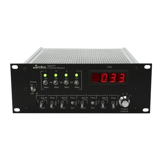
Four-Channel Mass Flow Controller Power Supply/Readout
Brand:
MKS
| Category:
Power Supply
| Size: 0 MB
Table of Contents
Table of Contents
5
Safety Information
13
Symbols Used in this Instruction Manual
13
Symbols Found on the Unit
14
Table 1: Definition of Symbols Found on the Unit
14
Safety Procedures and Precautions
15
Sicherheitshinweise
17
In dieser Betriebsanleitung Vorkommende Symbole
17
Am Gerät Angebrachte Symbole
18
Tabelle 2: Definitionen der am Gerät Angebrachten Symbole
18
Sicherheitsvorschriften und Vorsichtsmaßnahmen
19
Informations Relatives À la Sécurité
21
Symboles Utilisés Dans Ce Manuel D'utilisation
21
Symboles Apparaissant Sur L'appareil
22
Mesures de Sécurité Et Mises en Garde
23
Información sobre Seguridad
25
Símbolos Usados en el Manual de Instrucciones
25
Símbolos que Aparecen en la Unidad
26
Procedimientos y Precauciones de Seguridad
27
Chapter One: General Information
29
Introduction
29
How this Manual Is Organized
30
Customer Support
30
Chapter Two: Installation
31
How to Unpack the Type 247 Unit
31
Unpacking Checklist
31
Interface Cables
32
System Interface Cables
32
Table 5: System Interface Cables
32
Generic Shielded Cables
34
Product Location and Requirements
35
Operating Environmental Requirements
35
Safety Conditions
35
Setup
36
Dimensions
36
Figure 1: Front Panel Dimensions
36
Figure 2: Top View Dimensions
37
Power Requirements
38
Mounting Instructions
38
System Configurations
39
Figure 3: Manual Flow Control
39
Figure 4: Pressure Control with an External Controller
40
Electrical Information
42
Fuses
42
Grounding
42
Table 6: Fuse Information
42
How to Set the Line Voltage
43
Connectors and Cables
44
Interface Connector P6 (Channels 1 to 4)
44
Table 7: Interface Connector P6 (Channels 1 to 4) Pinout
44
Interface Connector P5 (Channel 1)
45
Table 8: Interface Connector P5 (Channel 1) Pinout
45
MFC Connectors (J1 - J4)
46
Table 9: MFC Interface Connectors (J1 - J4) Pinout
46
Chapter Three: Overview
47
General Information
47
Flow Signal Path
47
Set Point Signal
48
Set Point Signal Source
48
Set Point Function with Manual Flow Control
49
Set Point Function with External Flow Control
50
Set Point Function with Remote Flow Control
51
Front Panel Controls
52
Power ON/OFF Switch
52
Flow Indicator LED
52
Figure 5: Front Panel Controls
52
Flow Control Switch
53
Digital Panel Meter
53
Channel Selector
53
Set Point Source Switch
53
Set Point Control
54
Read / Set Point Switch
54
Zero Control
54
Rear Panel Controls
55
Scaling Control Potentiometers
55
Figure 6: Rear Panel Controls
55
Decimal Point Selector Switches
56
Line Voltage Selector
56
Fuse
56
AC Line Cord
56
Interface Connector J6 - Channels 1 to 4
56
Interface Connector J5 - Channel 1
57
MFC Connectors
57
Scaling Controls
58
Scaling Control Factor
59
Table 10: MFC Gauge Factors
59
Scaling Control Potentiometer
60
Figure 7: Scaling Control Potentiometer - Initial Setting
60
Gas Correction Factor (GCF)
61
How to Calculate the GCF for Pure Gases
62
How to Calculate the GCF for Gas Mixtures
63
Labels
65
Serial Number Label
65
Figure 8: Serial Number Label
65
Chapter Four: Operation
67
How to Setup the System
67
Table 11: Manual Flow Control - 247 Unit Front Panel Controls
67
Figure 9: Scaling Control Potentiometer - Example Setting
69
Manual Flow Control
71
How to Manually Control Individual Gas Flows
71
How to Manually Control Ratioed Gas Flows
73
Table 12: Ratio Control Set Point Levels
73
External Flow Control
75
How to Change the Dipswitch Settings
76
Table 13: Dipswitch S15 Initial Settings
76
Table 14: Dipswitch S15 Settings for +5 V Full Scale Input
76
Table 15: Dipswitch S15 Settings for +1 V Full Scale Input
77
How to Control Individual Gas Flows with an External Controller
78
How to Control Pressure with Ratioed Gas Flows
78
Table 16: External Controller - Front Panel Controls
79
Remote Flow Control
81
How to Control Gas Flow with TTL Logic
81
Chapter Five: Maintenance and Troubleshooting
83
General Information
83
Maintenance
83
How to Clean the Unit
83
How to Replace the Fuses
83
Troubleshooting
85
Power Supply
85
Channel Amplifiers
86
Internal +5 V Voltage Reference
87
External Ratio Amplifier
87
Digital Panel Meter
88
Set Point Buffer and Flow Switching Circuit
89
Appendix A: Product Specifications
91
Appendix B: Model Code Explanation
93
Model Code
93
Appendix C: Gas Correction Factors for Commonly Used Pure Gases
95
Table 17: Gas Correction Factors for Pure Gases
95
Index
99
Advertisement
Advertisement
Related Products
MKS 260 PS-7
MKS 260 PS-3B
MKS 246C
MKS 248A
MKS 248B
MKS 248C
MKS 2480HS
MKS 253B-20-2CF-2
MKS 250E
MKS Baratron 221B
MKS Categories
Controller
Measuring Instruments
Transducer
Control Unit
Industrial Equipment
More MKS Manuals
Login
Sign In
OR
Sign in with Facebook
Sign in with Google
Upload manual
Upload from disk
Upload from URL