Sign In
Upload
Manuals
Brands
MKS Manuals
DC Drives
1249A
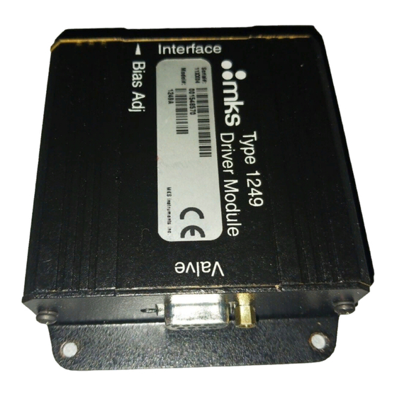
User Manuals: MKS 1249A Solenoid Valve Driver
Manuals and User Guides for MKS 1249A Solenoid Valve Driver. We have
1
MKS 1249A Solenoid Valve Driver manual available for free PDF download: Instruction Manual
MKS 1249A Instruction Manual (50 pages)
Solenoid Valve Driver
Brand:
MKS
| Category:
DC Drives
| Size: 0 MB
Table of Contents
Table of Contents
5
Valve Safety Information
9
Symbols Used in this Instruction Manual
9
Symbols Found on the Unit
10
Table 1: Definition of Symbols Found on the Unit
10
Safety Procedures and Precautions
11
Sicherheitshinweise für das Ventil
13
In dieser Betriebsanleitung Vorkommende Symbole
13
Erklärung der am Gerät Angebrachten Symbole
14
Tabelle 2: Bedeutung der am Gerät Angebrachten Symbole
14
Sicherheitsvorschriften und Vorsichtsmaßnahmen
15
Informations Relatives À la Sécurité Pour la Valve
17
Symboles Utilisés Dans Ce Manuel D'utilisation
17
Symboles Apparaissant Sur L'unité
18
Tableau 3: Définition des Symboles Apparaissant Sur L'unité
18
Mesures de Sécurité Et Précautions
19
Medidas de Seguridad de la Válvula
21
Símbolos Usados en Este Manual de Instrucciones
21
Símbolos Hallados en la Unidad
22
Tabla 4: Definición de Los Símbolos Hallados en la Unidad
22
Procedimientos y Precauciones de Seguridad
23
Chapter One: General Information
25
Introduction
25
How this Manual Is Organized
26
Manual Conventions
26
Customer Support
26
Chapter Two: Installation
27
How to Unpack the Type 1249 Unit
27
Unpacking Checklist
27
Interface Cables
28
Table 5: Interface Cables
28
Generic Shielded Cable Guidelines
29
Figure 1: Preferred Method to Connect an Overall Metal Braided Shielded Cable
30
Figure 2: Alternate Method to Connect an Overall Metal Braided Shielded Cable
30
Product Location and Requirements
31
Ambient Operating Temperature
31
Power Requirements
31
Setup
32
Dimensions
32
Figure 3: Top View Dimensions of the 1249 Unit
32
Mounting Instructions
33
Figure 4: Front View Dimensions of the 1249 Unit
33
Figure 5: Side View Dimensions of the 1249 Unit
33
Electrical Information
34
Grounding
34
Connectors
34
Table 6: Interface Connector Pinout
35
Table 7: Valve Connector Pinout
36
Chapter Three: Overview
37
General Information
37
Instrument Components
38
Interface Connector
38
Valve Connector
38
Figure 6: Instrument Components
38
Bias Adjust Potentiometer
39
Valve Position Indicator LED
39
Table 8: Valve Position Indicator Colors
39
On-Board Jumpers
40
Figure 7: Jumper Locations on the PC Board
40
Jumper J3 - Input Type
41
Jumper J4 - Full Scale Voltage
41
Jumper J5 - Digital Input Control
41
Table 9: Jumper Assignments
41
Labels
42
Serial Number Label
42
Figure 8: Serial Number Label
42
Table 10: Jumper Summary
42
Chapter Four: Operation
43
How to Set the Jumpers
43
How to Change the Bias Adjust Setting
44
Appendix A: Product Specifications
45
Performance Specifications
45
Electrical Specifications
46
Physical Specifications
46
Environmental Specifications
46
Appendix B: Model Code Explanation
47
Model Code
47
Index
49
Advertisement
Advertisement
Related Products
MKS Baratron 127A
MKS Baratron 128A
MKS 1253D
MKS Baratron 121A
MKS Baratron 122B
MKS Baratron 122A Series
MKS Baratron 122AA-00010
MKS Baratron 122AA-00100
MKS Baratron 122AA-01000
MKS 109030112
MKS Categories
Controller
Measuring Instruments
Transducer
Control Unit
Industrial Equipment
More MKS Manuals
Login
Sign In
OR
Sign in with Facebook
Sign in with Google
Upload manual
Upload from disk
Upload from URL