Sign In
Upload
Manuals
Brands
Mitsubishi Manuals
Controller
MELSEC iQ-F series
Mitsubishi MELSEC iQ-F series Manuals
Manuals and User Guides for Mitsubishi MELSEC iQ-F series. We have
2
Mitsubishi MELSEC iQ-F series manuals available for free PDF download: User Manual, Handbook
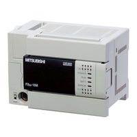
Mitsubishi MELSEC iQ-F series User Manual (184 pages)
Brand:
Mitsubishi
| Category:
Controller
| Size: 3.88 MB
Table of Contents
Safety Precautions
3
Introduction
9
Table of Contents
10
Relevant Manuals
16
Terms
17
Chapter 1 Outline
19
Part Names
19
Front Panel
19
Side
20
Chapter 2 Specifications
22
Generic Specifications
22
Power Supply Specifications
23
DC Power Supply
23
Input Specifications
24
DC Input (Sink/Source)
24
Output Specifications
26
Transistor Output
26
Input/Output Derating Curve
26
Performance Specifications
27
Communication Specifications
29
Built-In Ethernet Communication
29
Built-In RS-485 Communication
30
External Dimensions
30
CPU Module
30
Terminal Layout
31
Chapter 3 Product List
33
Overall Configuration
33
CPU Module
34
Extension Module
35
I/O Module
35
Intelligent Function Module
38
Extension Power Supply Module
40
Connector Conversion Module
40
Bus Conversion Module
41
Expansion Adapter
41
Extended Extension Cable and Connector Conversion Adapter
41
Extended Extension Cable
41
Connector Conversion Adapter
41
Terminal Module
42
SD Memory Card
42
Battery
42
Communication Cable
42
Engineering Tool
42
Chapter 4 System Configuration
43
Rules of System Configuration
44
Limitations on the Number of Connected Extension Devices
46
Number of Connected Expansion Adapters
46
Number of Connected Extension Modules (Including Extended Extension Cable)
46
Limitation on the Number of Input/Output Points
49
Total Number of I/O Points and Remote I/O Points
49
Calculation of the Number of Input/Output Points
49
Calculation of the Number of Remote I/O Points
50
Limitation on Current Consumption
52
Power Supply Check from the CPU Module (Current Consumption Calculation)
52
Power Supply Check from the Powered Input/Output Module (Current Consumption Calculation)
54
Power Supply Check from Extension Power Supply Module (Current Consumption Calculation)
55
Rules of System Configuration and Examples of Reconfiguration
57
System Configuration Example
57
System Reconfiguration Example
60
Numbers and Assignment in System
65
Module Input/Output Number
65
Module Number of Extension Modules
65
Chapter 5 Installation
66
Installation Location
66
Installation Location in Enclosure
66
Spaces in Enclosure
66
Layout in Enclosure
67
Examination for Installing Method in Enclosure
68
Procedures for Installing on and Detaching from DIN Rail
69
Preparation for Installation
69
Installation of CPU Module
69
Installation of Extension Modules (Extension Cable Type)
70
Installation of Terminal Modules
70
Removal of CPU Module
70
Procedures for Installing Directly (with M4 Screws)
71
Hole Pitches for Direct Mounting
71
Hole Pitches When Extension Module Connected
72
Installation of Extension Module (Extension Cable Type)
72
Connecting Methods for CPU Module and Extension Devices
73
Connection of Extension Devices
73
Connecting Method a - Connection of an Expansion Adapter
73
Connecting Method B - Connection of an Extension Module (Extension Connector Type)
74
Connecting Method C - Connection of a Connector Conversion Module (Extension Connector Type) or the Extension Power Supply Module and an Extension Module (Extension Cable Type)
75
Connecting Method D - Connection between Extension Modules (Extension Cable Type)
75
Connecting Method E - Connection of Extended Extension Cable and Connector Conversion Adapter
76
Connecting Method F - Connection of a Bus Conversion Module and an FX3 Intelligent Function Module
76
Connection of Power Cables
77
Removal of Power Cables
78
Connection of I/O Cables
78
Chapter 6 Wiring
80
Wiring Preparations
80
Wiring Procedure
80
Cable Connecting Procedure
81
European-Type Terminal Block
81
Screw Terminal Block
82
Grounding
83
Power Supply Wiring
84
Examples of DC Power Supply Wiring
84
Input Wiring
86
24 V DC Input
86
Input Wiring Example
91
Input Wiring Examples of Terminal Modules
94
Output Wiring
96
Transistor Output
96
Relay Output
99
Triac Output
102
Output Wiring Example
104
Output Wiring Examples of Terminal Modules
107
Examples of Wiring for Various Uses
111
Positioning Function
111
Communication Function
111
High-Speed Counter
111
Interruption
114
Digital Switch
115
Input Matrix
117
Seven Segment with Latch
118
Chapter 7 Operation Adjustment
120
Preparation for Operation
120
Preliminary Inspection
120
Procedure until Operation
120
Connection with a Personal Computer
121
Operation and Test
122
Self-Diagnostic Function
122
Monitoring and Debugging
122
Running, Stopping, and Resetting
123
Methods of Running, Stopping, and Resetting
123
Chapter 8 Maintenance and Inspection
124
Daily Inspection
124
Periodic Inspection
124
Battery
125
Part Names
125
Specifications
125
Battery Attachment
125
Battery Replacement
126
Special Relay for Low Battery Voltage
128
Chapter 9 Troubleshooting
129
Troubleshooting Procedure
129
Checking with Leds
129
Checking the PWR LED
129
Checking the BAT LED
129
Checking the ERR LED
130
Checking the P.RUN LED
130
Troubleshooting Using the Engineering Tool
131
Module Diagnostics (CPU Diagnostics)
131
Event History
132
Error Status and Operations on Occurrence of an Error
133
Backing up the Data
134
Canceling Errors
134
Troubleshooting for each Symptom
135
I/O Operation (CPU Module, I/O Module)
135
PLC Write, PLC Read
136
Boot Operation
136
Appendix
137
Appendix 1 How to Check the Date of Manufacture
137
Appendix 2 Standards
138
Certification of UL, Cul Standards
138
Compliance with EC Directive (CE Marking)
138
Requirement for Compliance with EMC Directive
138
Requirement for Compliance with LVD Directive
139
Caution for Compliance with EC Directive
139
Appendix 3 Precautions for Operating Ambient Temperature
141
Appendix 4 I/O Module
142
Product Configuration
142
Product List
142
Specifications
144
External Dimensions and Component Names
152
Terminal Layout
157
Appendix 5 Connector Conversion Module
159
External Dimensions and Component Names
159
Specifications
159
Appendix 6 SD Memory Card
160
Part Names
160
Specifications
160
Insertion and Removal of the SD Memory Card
161
Appendix 7 Terminal Module
162
Product Configuration
162
Product List
162
Specifications
163
External Dimensions and Component Names
168
Terminal Layout
169
Internal Circuit
170
Appendix 8 Precautions for Battery Transportation
176
Control-Subject Product
176
Precautions for Transportation
176
Appendix 9 Handling of Batteries and Devices with Built-In Batteries in EU Member States
177
Disposal Precautions
177
Exportation Precautions
177
Appendix 10Added and Changed Functions
178
Index
179
Revisions
180
Warranty
181
Trademarks
182
Advertisement
Mitsubishi MELSEC iQ-F series Handbook (60 pages)
Brand:
Mitsubishi
| Category:
Controller
| Size: 0.82 MB
Table of Contents
Safety Precautions
3
Introduction
10
Table of Contents
12
Relevant Manuals
14
Terms
16
CHAPTER 1 Outline
18
Outline of the MELSEC Iq-F Series
18
Outstanding Performance
18
Superior Drive Control
18
Improved Programming Environment
18
Substitute Models
19
Selection and Replacement of the Models
19
Replacement of the Projects
19
CHAPTER 2 Replacement from FX3U to FX5U
20
Outline
20
Replacement Procedure
20
Selection of Substitute Models
21
Recommended Substitute Models
21
Precautions Regarding the Hardware
25
Conversion of the Projects
26
Replacement of the PLC
26
CHAPTER 3 Replacement from FX3UC to FX5UC
27
Outline
27
Replacement Procedure
27
Selection of Substitute Models
28
Recommended Substitute Models
28
Precautions Regarding the Hardware
31
Conversion of the Projects
33
Replacement of the PLC
33
CHAPTER 4 Conversion of the Projects
34
Operation Method for Replacing Projects
34
Precautions When Converting the Projects
38
Instruction Replacement List
38
Precautions for Instruction Replacement
46
Device Replacement List
48
Precautions for Device Replacement
50
Precautions When Replacing the Parameters
50
Precautions When Replacing Other Functions
51
Precautions When Using the High-Speed Counters
51
Precautions When Using the Routine Timer
53
Index
54
Revisions
56
Warranty
57
Trademarks
58
Advertisement
Related Products
Mitsubishi MELSEC iQ-F
Mitsubishi MELSEC iQ-R series
Mitsubishi MELSEC Q Mode
Mitsubishi MELSEC-F Series
Mitsubishi MELSEC-QX48Y57
Mitsubishi MELSEC-A6CON4
Mitsubishi MELSEC-QX80-TS
Mitsubishi MELSEC-QX80-H
Mitsubishi MELSEC-L60AD4
Mitsubishi MELSECNET/10 A1SJ72QLP25
Mitsubishi Categories
Air Conditioner
Controller
Projector
Automobile
Engine
More Mitsubishi Manuals
Login
Sign In
OR
Sign in with Facebook
Sign in with Google
Upload manual
Upload from disk
Upload from URL